Process for large-scale production of cdte/cds thin film solar cells

a technology of cdte/cds and solar cells, which is applied in the direction of photovoltaic energy generation, ion implantation coatings, coatings, etc., can solve the problems of affecting the achievement, affecting the stability of the target, and damage to the film, and achieve stable and efficient cdte/cds, large-scale production, and low cost

Inactive Publication Date: 2004-12-09
ARENDI
View PDF4 Cites 25 Cited by
  • Summary
  • Abstract
  • Description
  • Claims
  • Application Information

AI Technical Summary

Benefits of technology

0014] It is the main object of the present invention to provide a process suitable for a large-scale production of stable and efficient CdTe / CdS thin film solar cells on a low cost substrate.

Problems solved by technology

However, this material is made by sputtering and the ITO target after several runs forms some noodles which contain an In excess and a discharge between noodles can happen during sputtering which can damage the film.
Also this material has some drawbacks since the target is made up of a mixture of CdO and SnO.sub.2 and, being CdO highly hygroscopic, the stability of the target may result to be unsatisfactory.
However, a number of problems still hinder the achievement of this result, in particular concerning some crucial steps which affect either stability and efficiency of CdTe / CdS thin film solar cells or their costs.
A major problem of the known processes is the etching step to which the CdTe surface must be submitted to remove CdO or CdTeO.sub.3 oxides formed thereon.
Another significant problem which negatively affects the stability of the TCO films, as well as the cost of the final product are the drawbacks presently encountered with the use of known TCOs, as previously mentioned.
In addition to these drawbacks, known TCOs require the use of special glasses, such as borosilicate glass, to avoid the problem of Na diffusion, occurring if a soda-lime glass is used, which would damage the film.
A further problem concerns the source from which the CdS film and the CdTe film are produced by close-spaced sublimation.
In order to avoid this inconvenience, complicated metallic masks are used in some cases, which make a continuous operation problematic.

Method used


Image

  • Process for large-scale production of cdte/cds thin film solar cells
  • Process for large-scale production of cdte/cds thin film solar cells
  • Process for large-scale production of cdte/cds thin film solar cells

Examples


example

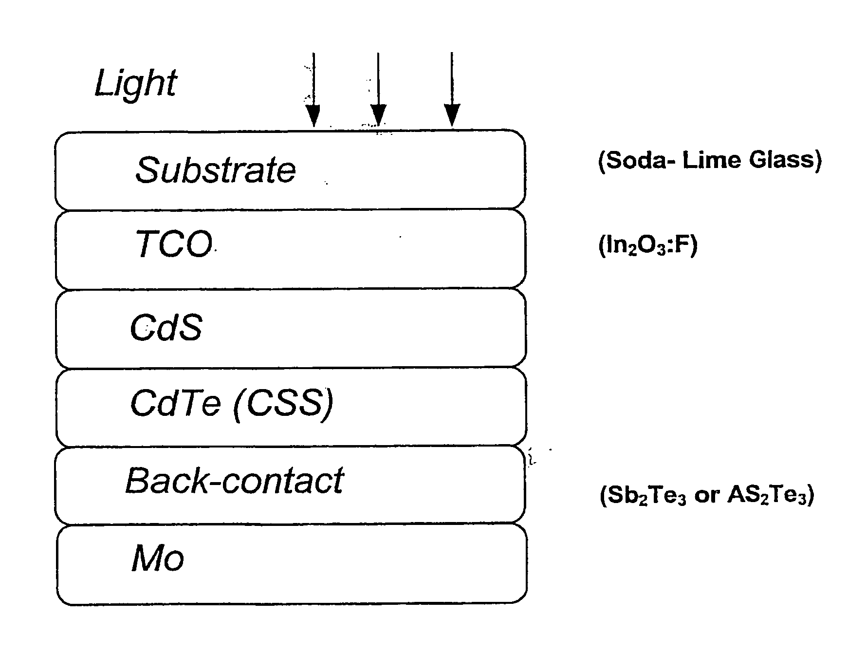
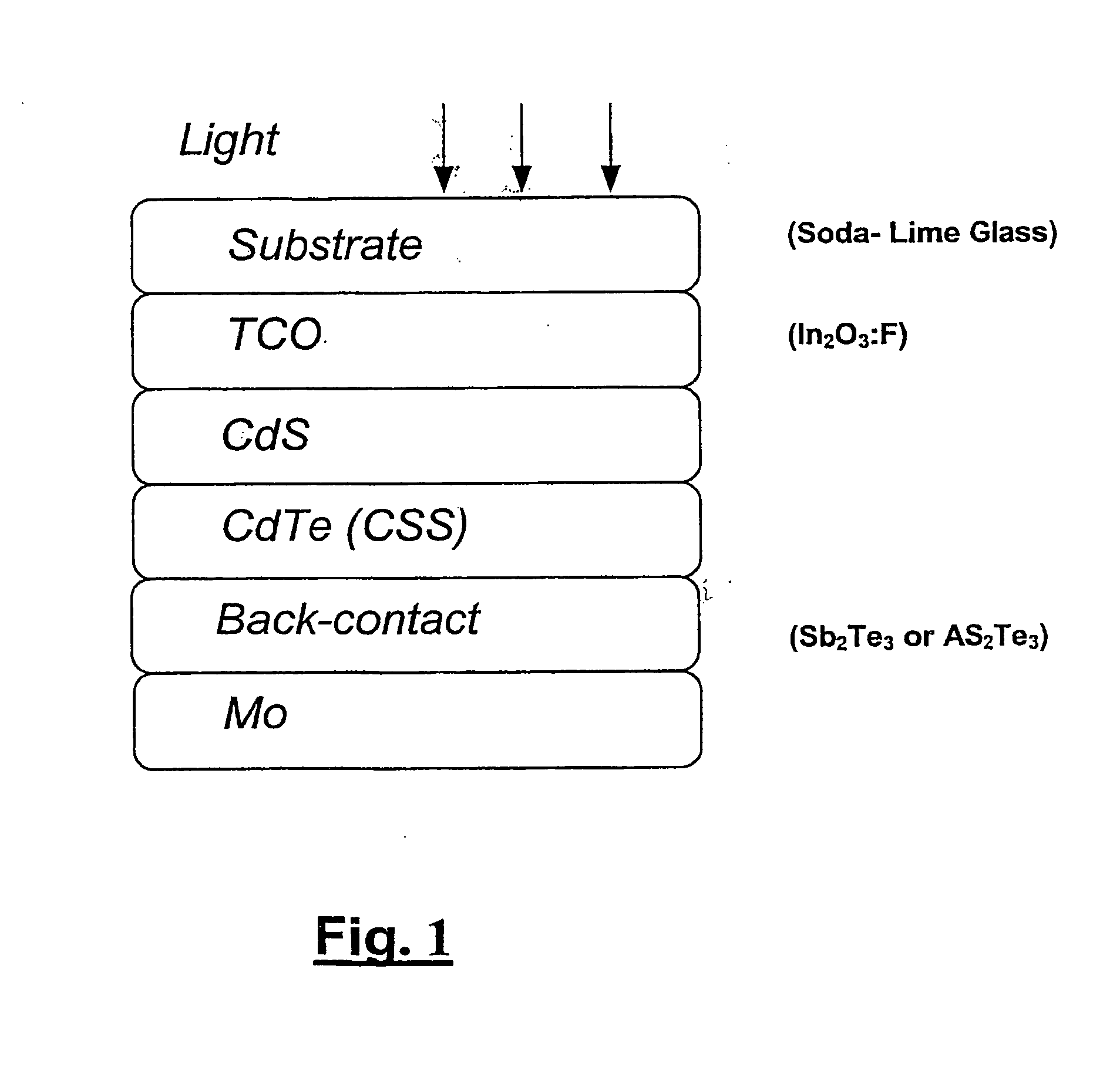
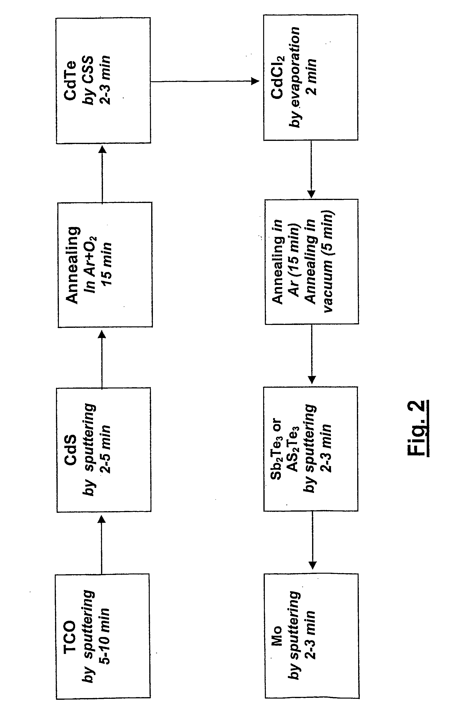
[0038] A cell exhibiting a 14% efficiency has been prepared in the following way: a soda-lime glass has been covered by 500 nm of In.sub.2O.sub.3:F (fluorine-doped) deposited at 500.degree. C. substrate temperature as described above. 100 nm of CdS have been deposited by sputtering at 300.degree. C. substrate temperature and annealed for 15 min at 500.degree. C. in 500 mbar of Ar containing 20% of O.sub.2. 8 .mu.m of CdTe have been deposited on top of CdS by CSS at a substrate temperature of 500.degree. C. Both CdS and CdTe films are produced from a compact block source as described above. A treatment with 150 nm of CdCl.sub.2 has been done in an Ar atmosphere as described above. Finally a back contact has been created, without any etching, by depositing in sequence by sputtering 150 nm of Sb.sub.2Te.sub.3 and 150 nm of Mo.

[0039] After one hour under 10 suns at a temperature of 180.degree. C. in open-circuit conditions the solar cell prepared in this way exhibited the following para...


PUM

PropertyMeasurementUnit
pressureaaaaaaaaaa
pressureaaaaaaaaaa
temperatureaaaaaaaaaa

Abstract

A process for large-scale production of CdTe/CdS thin film solar cells, films of the cells being deposited, in sequences on a transparent substrate, the sequence comprising the steps of: depositing a film of a transparent conductive oxide (TCO) on the substrate; depositing a film of CdS on the TCO film; depositing a film of CdTe on the CdS film; treating the CdTe film with CdCl2; depositing a back-contact film on the treated CdTe film. Treatment of the CdTe film with CdCl2 comprises the steps of: forming a layer of CdCl2 on the CdTe film by evaporation, while maintaining the substrate at room temperature; annealing the CdCl2 layer in a vacuum chamber at a temperature generally within a range of 380° C. and 420° C. and a pressure generally within a range of 300 mbar and 1000 mbar in an inert gas atmosphere; removing the inert gas from the chamber so as to produce a vacuum condition, while the substrate is kept at a temperature generally within a range of 350° C. and 420° C. whereby any residual CdCl2 is evaporated from the CdTe film surface.

Description

[0001] The present invention relates to the field of the solar cells technology and more particularly concerns a process for the large-scale production of CdTe / CdS thin film solar cells.BACKGROUND ART OF THE INVENTION[0002] As is known, a typical configuration of a CdTe / CdS solar cell has a film sequence of the multi-layer arrangement comprising a transparent glass substrate carrying a transparent conductive oxide (TCO) film, a CdS film representing the n-conductor, a CdTe film representing the p-conductor and a metallic back-contact. A solar cell with a layer arrangement and structure of this type is disclosed, for example, in U.S. Pat. No. 5,304,499.[0003] The commercial float glass may be used as a transparent substrate, but, in spite of its low cost, special glasses are often preferred to avoid drawbacks of the float glass, in particular Na diffusion into TCO film.[0004] The most common TCO is In.sub.2O.sub.3 containing 10% of Sn (ITO). This material has a very low resistivity o...

Claims


Application Information

Patent Timeline
Patent Type & Authority Applications(United States)
IPC IPC(8): C23C14/06C23C14/08C23C14/58H01L21/20H01L21/363H01L21/477H01L31/0224H01L31/04H01L31/073H01L31/18
CPCC23C14/0629C23C14/086C23C14/5806H01L31/022425H01L31/073H01L31/1828H01L31/1884Y02E10/543Y02P70/50
Inventor ROMEO, NICOLABOSIO, ALESSIOROMEO, ALESSANDRO
Owner ARENDI
Why Eureka
Try Eureka