Measurement of air characteristics in the lower atmosphere

a technology of air characteristics and air, applied in the direction of analyzing fluids using sonic/ultrasonic/infrasonic waves, using reradiation, processing detected response signals, etc., can solve the problems of inadequate signal-to-noise ratio, degradation of doppler sodar performance, and inability to meet the promise of methods, etc., to achieve uniform phase shift rate, convenient processing, and easy generation

Inactive Publication Date: 2004-12-16
TELE IP
View PDF6 Cites 27 Cited by
  • Summary
  • Abstract
  • Description
  • Claims
  • Application Information

AI Technical Summary

Benefits of technology

[0010] This avoids the need to limit pulse length to secure near-range capability, which is essential in known pulsed sodars that employ the `transmit then listen` strategy. For example if the pulse length of a conventional sodar is one second, the first 170 m of range will be lost because the receiver will be turned off for the first second; a 10 s pulse will lose the first 1700 m of range. Typically, therefore, pulsed sodars of the art employ pulses of a few tens of milliseconds. By contrast, our chirps are of at least 300 ms duration and, preferably longer than 10 s; indeed, we have used chirps of up to 50 s, the duration only being limited by our current signal processing capacity. Preferably, the duration of the chirp is at least 5% of the listening time; that is, there is at least 5% overlap between chirp transmission and echo reception, but it will be appreciated that listening time depends on the distance range covered. For ranges up to a few km, we prefer chirp lengths well over 50% of receive time. As a convenient guide, we listen for about 6 s longer than the chirp for each km of range. Thus, in a system with a 1 km range, the chirp / pulse duration might be 15 s and the listening time 21 s; for a 2 km range, we might use a 31 s chirp and listen for 43 s. Generally, we start listening at the commencement of the chirp transmission to obtain data from ground level up. For some applications however we may not want the ground level data and choose to start listening some time after the end of the chirp transmission.
[0027] Although (as already noted) long duration chirps offer the potential of high system processing gains (lower s / n), long chirps also result in significant computational demands when using the high signal sampling rates and the Fourier techniques needed to achieve such gains. We have found that current readily available FFT algorithms, DSP chips and PCs set a practical limit on chirp duration of about 40-50 s at sampling rates of about 96 k Hz. This typically represents some 1400 samples per m, given a range of 3000 m. Indeed, the computational demands are such that we prefer to dedicate one PC to each receiver of a multi-receiver system so that echo analysis for all receiver signals can proceed in parallel to the point where signal differencing takes place. In the future, developments in chips, FFT / matched filter techniques and PCs may allow longer chirps to be processed using a single PC--or, much faster updating times using the pulse lengths presently achievable.

Problems solved by technology

Though exclusively acoustic methods for wind profiling and the like have a long history, Coulter & Kallistratova in their 1999 article "The Role Acoustic Sounding in a High-Technology Era" [Meteorol. Atmos. Phys. 71, 3-19] show that these methods have not lived up to their promise.
This appears to have been largely due to an inability to achieve an adequate signal-to-noise ratio [s / n].
Despite the application of such sophisticated techniques to sodar, a review by Crescenti entitled, "The Degradation of Doppler Sodar Performance Due to Noise" [Crescenti, G. H., 1998, Atmospheric Environment, 32, 1499-1509], found that severe problems remain even at modest ranges of 1500 m.

Method used


Image

  • Measurement of air characteristics in the lower atmosphere
  • Measurement of air characteristics in the lower atmosphere
  • Measurement of air characteristics in the lower atmosphere

Examples


Embodiment Construction

[0028] Having portrayed the nature of the present invention, particular examples will now be described with reference to the accompanying drawings. However, those skilled in the art will appreciate that many variations and modifications can be made to the chosen examples while conforming to the scope of the invention as outlined above.

[0029] In the accompanying drawings:

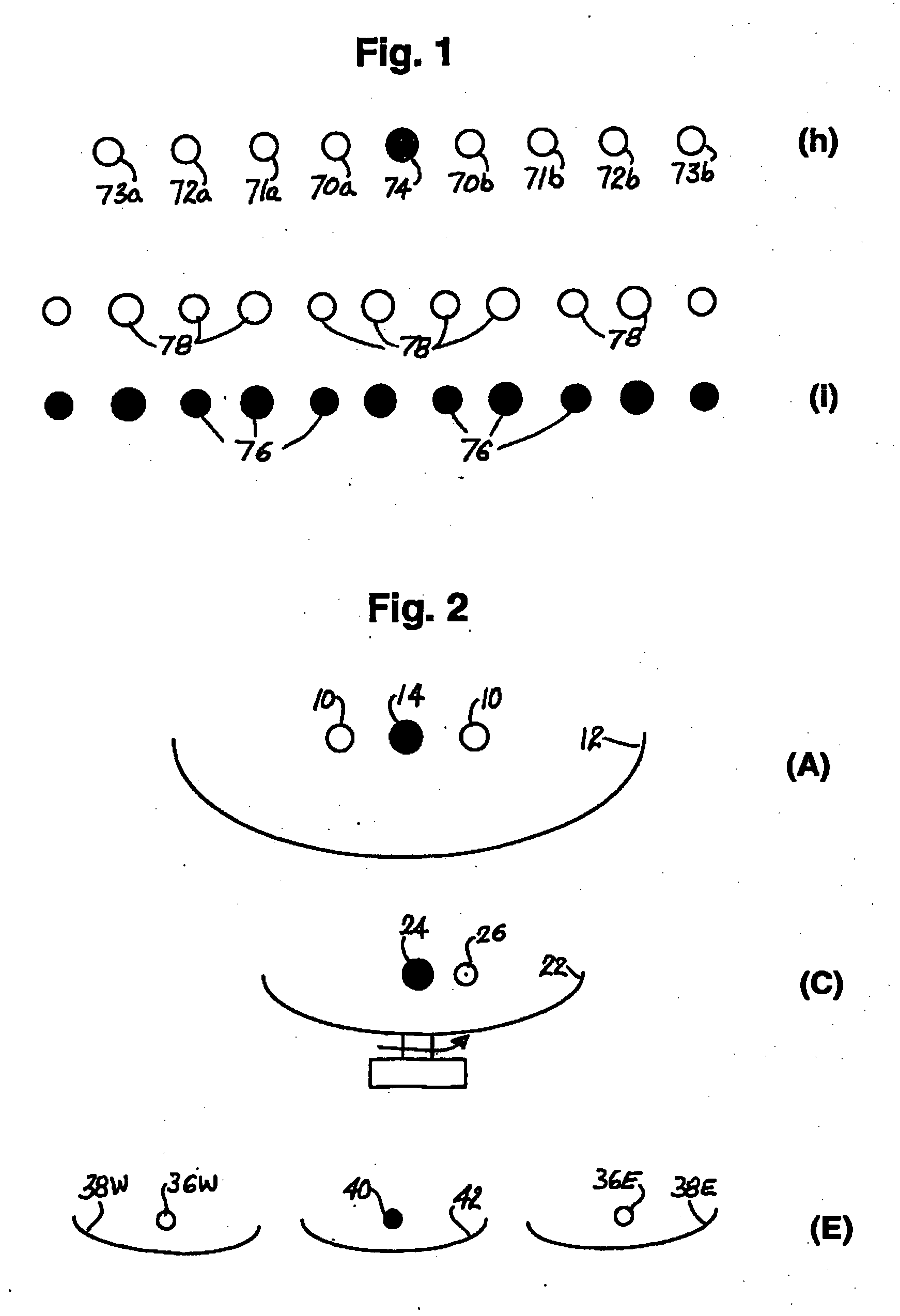
[0030] FIG. 1 is a series of diagrammatic plan views showing selected arrangements of transmitters and receivers, the transmitters (loudspeakers) being shown as small shaded circles and the receivers (microphones) being shown as small unshaded circles.

[0031] FIG. 2 is a series of diagrammatic elevations showing co-located and separately located transmitter and receiver arrangements.

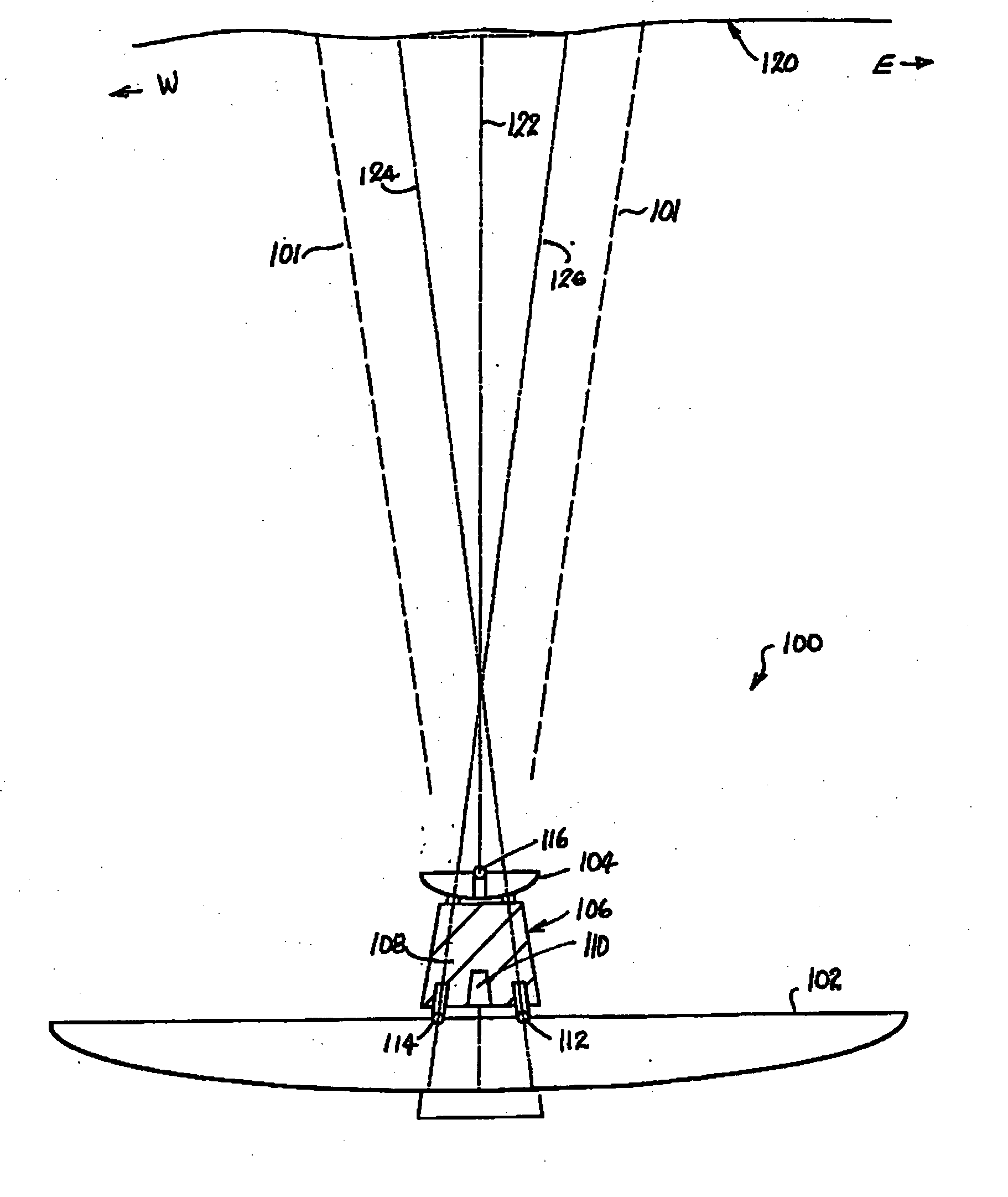
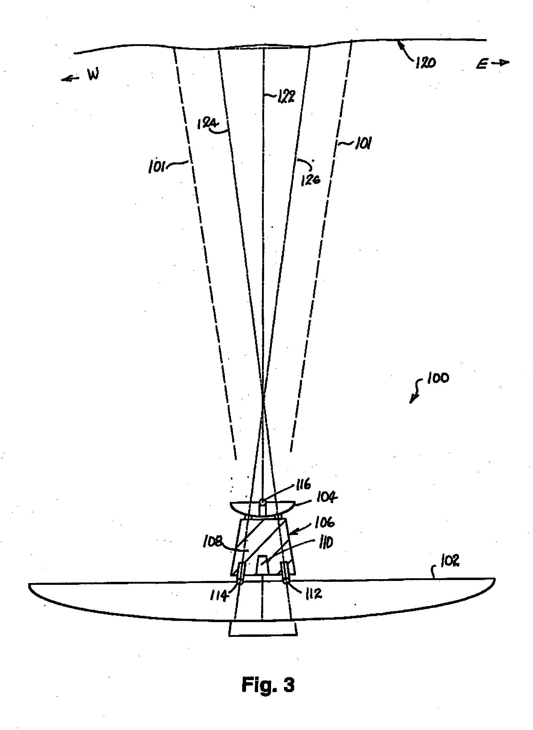
[0032] FIG. 3 is a diagrammatic sectional elevation showing the arrangement of the transmitter and receivers of the first system example.

[0033] FIG. 4 is a schematic plan of the system of FIG. 3 showing the general manner in which signals ...


PUM

PropertyMeasurementUnit
angleaaaaaaaaaa
angleaaaaaaaaaa
pulse lengthaaaaaaaaaa

Abstract

Sodar systems and methods for acoustically sounding air are disclosed in which chirps longer than 300 ms-and preferably with durations of tens of seconds-are used along with matched filter and / or Fourier processing methods to derive phase signals indicative of air characteristics in range. A listen-while-transmit strategy is preferred, the direct signal being removed by subtracting the phase signals from two or more receivers located near the transmitter so as to be in the same noise environment. The resultant differential signals can be related to cross-range wind with range distance. In one example, apparatus (100) is employed comprising a reflector dish (102) over which one central loudspeaker (110) and four microphones (112, 114, 130 and 132) are mounted, the microphones preferably being located on cardinal compass points and having their axes (124, 126) slightly angled with respect to the vertical transmission axis (122).

Description

[0001] This application is a continuation of international Application Serial No. PCT / AU02 / 01129 filed 19 Aug. 2002, published under PCT Article 21(2) in English; and claiming priority from Australian patent applications PR 7203 filed 23 Aug. 2001 and PR 7832 filed 21 Sep. 2001, and applicant claims the benefit of Australian patent applications PR 7203 filed 23 Aug. 2001 and PR 7832 filed 21 Sep. 2001.[0002] This invention relates to the use of acoustic signals for atmospheric sounding and is particularly concerned with sodar techniques for measuring air velocity variation--such as horizontal wind speed variation, wind-shear and / or turbulence--in the lower atmosphere. The invention may, however, be applied to measuring local density variation in the atmosphere, such as may be caused by temperature gradients, temperature, thermal inversions and variations in moisture content.[0003] The apparatus and methods of the intention are also applicable to wind profiling in the vicinity of air...

Claims


Application Information

Patent Timeline
Patent Type & Authority Applications(United States)
IPC IPC(8): G01N29/02G01N33/00G01N29/24G01N29/46G01P5/24G01S7/526G01S15/10G01S15/58G01S15/87G01S15/88G01W1/00G01W1/02
CPCG01N29/02G01N29/2456G01N29/46G01N2291/012G01N2291/045G01N2291/103G01P5/24G01S15/104G01S15/582G01S15/87G01S15/885G01W2001/003
Inventor MARTIN, ANDREW LOUIS
Owner TELE IP
Why Eureka
Try Eureka