
Polymer alloy and method for manufacturing polymer alloy

a polymer alloy and polymer alloy technology, applied in the field of polymer alloy manufacturing methods, can solve the problems of poor spinning stability during spinning, difficult control of dispersion size for making it small, and inability to achieve satisfactory effects in improving strength, toughness and heat resistance of molded objects

Active Publication Date: 2004-12-30
TORAY IND INC
View PDF7 Cites 15 Cited by
  • Summary
  • Abstract
  • Description
  • Claims
  • Application Information

AI Technical Summary

Benefits of technology

This patent describes a method for making a polymer alloy by blending two resins that can be separated into phases under no shear flow. The resins are made miscible by melt blending and then undergo spinodal decomposition to form a co-continuous structure or a dispersed structure with a specific distance between particles. The resulting polymer alloy has improved mechanical properties and can be used in various applications such as film, sheet, and molded article. The patent also provides examples of different polymer alloy compositions that can be made using this method.

Problems solved by technology

However, according to the method described in the document, satisfactory effects could not be achieved in improving the strength, toughness and heat resistance of the molded article.
However, according to the method described in the document, it was difficult to control the dispersion size for making it small.
Furthermore, if the dispersion size in a polymer alloy is large, there arise such problems that in the case where the polymer alloy is used as fibers, the spinning stability during spinning is poor, and that voids are formed during stretching, to make the fibers fragile.
However, according to the method described in the document, because of the mechanism, in which the fibers obtained by spinning a polymer blend in its miscible state are heat-treated for causing phase separation, there was a limit in controlling the structure for making it finely dispersed.
Furthermore, there was a limit in applicable combinations of polymers, and the form of the polymer blend was also limited to fibers.

Method used


Image

  • Polymer alloy and method for manufacturing polymer alloy
  • Polymer alloy and method for manufacturing polymer alloy
  • Polymer alloy and method for manufacturing polymer alloy

Examples


working examples 1 to 5

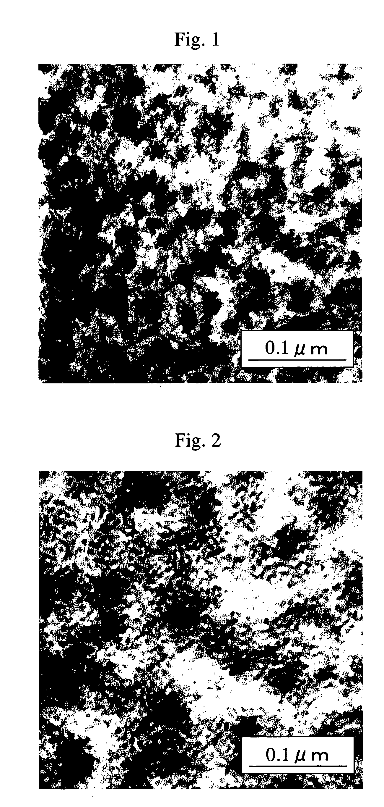
[0170] Raw materials with a composition ratio shown in Table 1 were fed into a parallel plates type shear flow-applying device (CSS-430 produced by Linekam), and molten at a kneading temperature of 250.degree. C. Then, a shear field was applied at the shear rate shown in Table 1. Every sample was observed in the portion subjected to the shear field at the shear rate shown in Table 1, and it was confirmed that none of the samples had any structure. Each of the samples was immediately quickly cooled in icy water to fix its structure, and the phase structure of the obtained sample was observed with a transmission electron microscope. It was confirmed that none of the samples had structure of 0.001 .mu.m or more, and that they were made miscible. So, it was found that this series was made miscible at 250.degree. C. under the shearing condition shown in Table 1.

[0171] Next, raw materials with a composition ratio shown in Table 1. were fed into a twin-screw extruder (PCM-30 produced by Ik...

working examples 6 and 7

[0185] Raw materials with a composition ratio shown in Table 2 were fed into a parallel plates type shear flow-applying device (CSS-430 produced by Linekam), and molten at a kneading temperature of 240.degree. C. Then, a shear field was applied at the shear rate shown in Table 2. Every sample was observed in the portion subjected to the shear field at the shear rate shown in Table 2, and it was confirmed that none of the samples had any structure. Each sample was immediately quickly cooled in icy water, to obtain a sample with its structure fixed. The phase structure of the obtained sample was observed with a transmission electron microscope. It was confirmed that none of the samples had structure of 0.001 .mu.m or more, and that they were made miscible. So, it was found that this series was of a system that could be made miscible at 240.degree. C. under the shearing condition shown in Table 2.

[0186] Raw materials with a composition ratio shown in Table 2 were fed into a twin-screw ...

working examples 13 to 15

[0204] Melt blending was carried out to obtain pellets as described for Working Examples 8 to 10, except that a die with a large inner volume was used. The retention time in the die was 20 seconds. In the observation made using a transmission electron microscope as described for Working Examples 8 to 10, fine co-continuous structures were observed. The wavelengths of concentration fluctuation obtained using small-angle X-ray scattering are shown in Table 3. The molded articles were evaluated as described for Working Examples 8 to 10, and the results are shown in Table 3.

3TABLE 3 Working Working Working Working Example 8 Example 9 Example 10 Example 11 Composition PBT-2 parts by 75 55 25 55 weight PC-2 parts by 25 45 75 45 weight Releasing agent parts by -- -- -- 0.2 (internally added) weight Releasing agent parts by -- -- -- -- (externally added) weight Kneading Temperature .degree. C. 260 260 260 260 conditions Screw speed rpm 300 300 300 300 Dwell time in die sec 5 5 5 5 Cooling b...


PUM


Abstract

This invention is a method for manufacturing a polymer alloy, by making at least two resins used as components miscible, and inducing the spinodal decomposition for causing phase separation, for forming a co-continuous structure with a wavelength of concentration fluctuation of 0.001 to 1 mum or a dispersed structure with a distance between particles of 0.001 to 1 mum. This invention is also a polymer alloy manufactured by the method. The polymer alloy of this invention can provide a molded article, film, fibers and the like respectively with excellent mechanical properties at high productivity.

Description

[0001] 1. Technical Field[0002] The present invention relates to a method for manufacturing a polymer alloy having a phase-separated structure consisting of at least two components, polymer alloy pellets, a polymer alloy film or sheet, a molded polymer alloy article, a polymer alloy containing polybutylene terephthalate resin and a polycarbonate resin, and a polymer alloy containing polyphenylene sulfide resin and a polyester resin with polyethylene terephthalate as a main component.[0003] 2. Background Art[0004] JP5-156141A describes a molded article having a inter penetrating network structure obtained by melt blending polybutylene terephthalate resin, a polycarbonate resin, and acrylic graft (co)polymer particles. It is disclosed that this structure improves chemicals resistance, strength and toughness to some extent compared with a simple polymer alloy. However, according to the method described in the document, satisfactory effects could not be achieved in improving the strengt...

Claims


Application Information

Patent Timeline
Patent Type & Authority Applications(United States)
IPC IPC(8): C08J3/00C08L67/02C08L69/00
CPCC08J3/005C08L67/02C08L69/00C08L81/02C08L2666/18
Inventor KOBAYASHI, SADAYUKIKUMAKI, JIROHIRAI, AKIRANISHIMURA, TORU
Owner TORAY IND INC
Learn More