Solar cell module having an electric device

a solar cell module and electric device technology, applied in the field of solar cell modules, can solve the problems of increasing manufacturing costs, complex methods, and unsuitable automation, and achieve the effects of low cost, high reliability, and simple manufacturing methods

Inactive Publication Date: 2005-01-06
CANON KK
View PDF53 Cites 68 Cited by
  • Summary
  • Abstract
  • Description
  • Claims
  • Application Information

AI Technical Summary

Benefits of technology

[0009] The present invention has been made in view of the above circumstances, and it is an object of the present invention to provide a solar cell module which can be manufactured at low cost, from which electricity generated by solar cell elements can be efficiently extracted, and to which an electric device connected to the elements can be securely fixed.
[0011] A solar cell module of the present invention includes a front member placed at a light-incident side of the solar cell module; a sealing member having an exposed section that is not covered with the front member; solar cell elements that are sealed with the sealing member and covered with the front member; and an electric device, stored in a housing, for extracting electricity generated by the solar cell elements. The housing is fixed on the exposed section and is located at the light-incident side of the solar cell module. According to the above configuration, since the electric device is securely fixed to the exposed section, the electric device can be prevented from being detached from the exposed section and the electrical insulation of the lead electrodes and electric device can be prevented from being deteriorated if the solar cell module is exposed outdoors over a long period. Therefore, the solar cell module has high reliability.
[0012] In the solar cell module, the exposed section preferably extends out past an outer edge of the front member. In order to expose a portion of the sealing member from the front member, a slit opening may be formed in the front member before the solar cell elements are sealed. In such a method, the lead electrodes for extracting the electricity generated by the solar cell elements must be aligned with the slit opening when the solar cell elements, the sealing member, and the front member are stacked. Therefore, the method is complicated and is not fit for automation. However, in the present invention, the exposed section preferably extends out past an outer edge of the front member and the alignment is not therefore necessary; hence, a method for manufacturing the solar cell module is simple and the solar cell module can be manufactured at low cost. When the front member is made of glass, the formation of the opening in the front member causes an increase in manufacturing cost. However, in the present invention, the exposed section preferably extends out of the front member and the opening need not be therefore formed in the glass front member; hence, manufacturing cost is not high.
[0013] Electrical wiring members connected to the electric device may be fixed on the exposed section, whereby an external force exerted on the electrical wiring members is not directly transmitted to the electric device. Therefore, the electric device can be securely fixed to the exposed section and the reliability of the electric device is high.
[0014] A moisture-proof layer may be placed between the electric device and the sealing member, whereby moisture passing through the sealing member can be prevented from penetrating the electric device; hence, moisture can be prevented from lowering the adhesion of the housing, which stores the electric device, to the sealing member. Furthermore, moisture can be prevented from corroding wiring members placed in the electric device. If the moisture-proof layer includes a metal sheet, heat generated by the electric device can be released through the metal sheet.
[0015] According to the above configuration, an electrode-routing section and electric device-fixing section of the solar cell module have high reliability and can be formed at low cost. Furthermore, the solar cell module can be manufactured at low cost by a simple method. The electric device can be securely fixed to the exposed section, whereby the reliability of the electric device is ensured. Therefore, the electric device can be prevented from being detached from the exposed section and the insulation of the lead electrodes and the electric device can be prevented from being deteriorated if the solar cell module is exposed over a long period.

Problems solved by technology

Therefore, the method is complicated and is not fit for automation.
When the front member is made of glass, the formation of the opening in the front member causes an increase in manufacturing cost.

Method used


Image

  • Solar cell module having an electric device
  • Solar cell module having an electric device
  • Solar cell module having an electric device

Examples


example 1

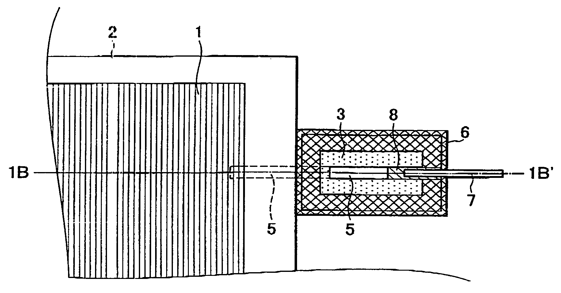
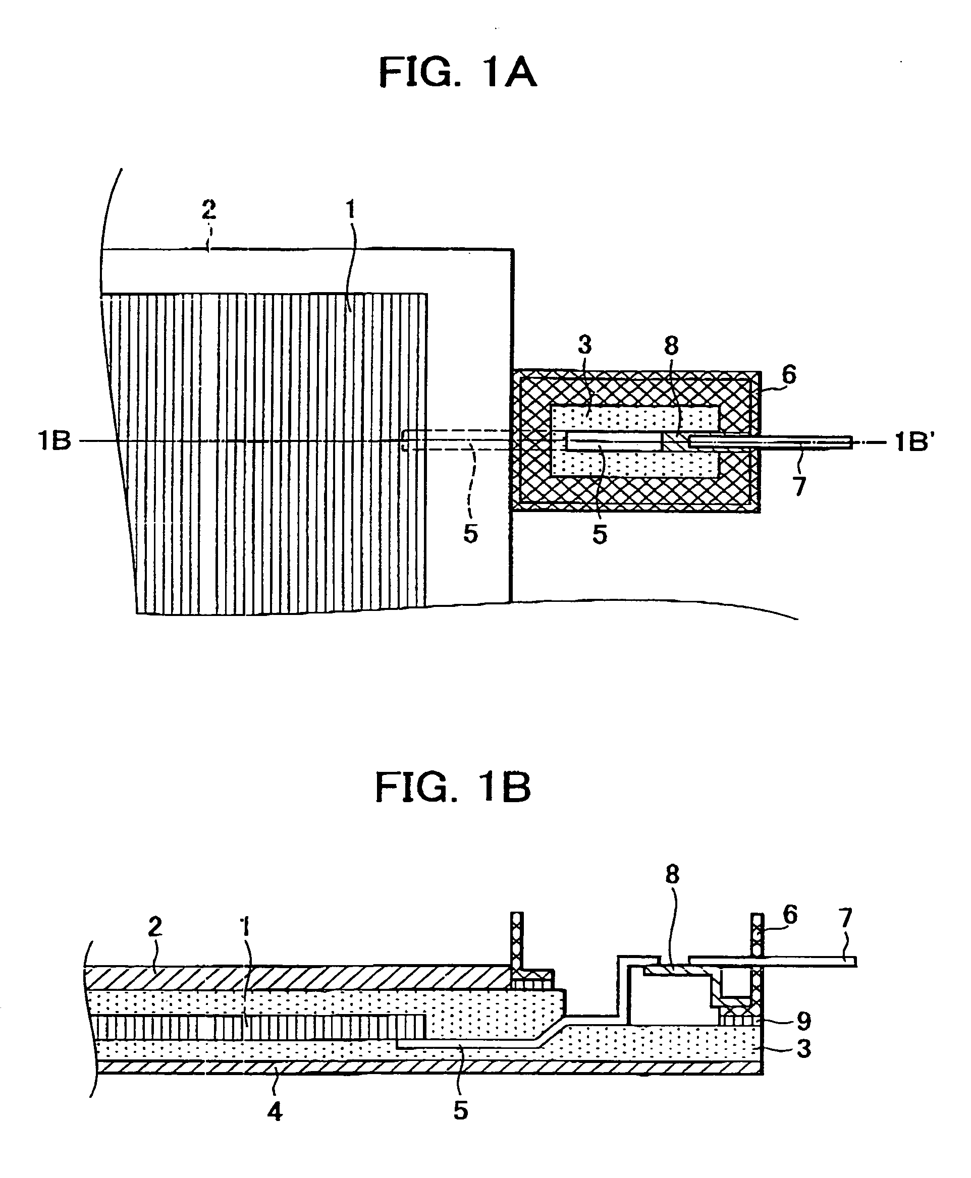
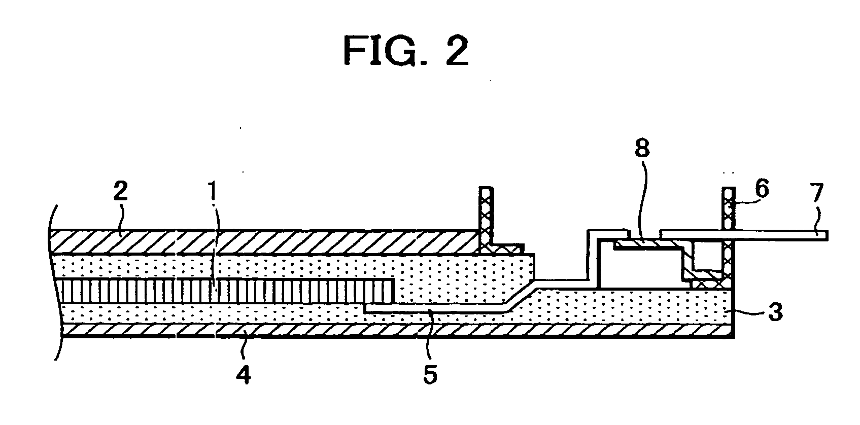
[0048] A procedure for manufacturing a solar cell module according to an embodiment of the present invention is described below with reference to FIGS. 5, 7A, 7B, and 8. The solar cell module includes a plurality of solar cell elements 1 (amorphous silicon solar cells) each including corresponding conductive substrates, rear reflecting layers, semiconductor photoactive layers, transparent electrode layers disposed in that order and further includes interdigital collector electrodes placed on the transparent electrode layers and a bus bar electrode connected to the comblike collector electrodes.

[0049] The solar cell elements 1 are connected in series. One of the lead electrodes 5 each including a tin plated copper sheet is soldered to an electrode connected to an end of the series of solar cell elements 1.

[0050] As shown in FIG. 8, the following components are stacked on a polyester film 84 having a thickness of 100 μm in this order: a first sheet 832 having a thickness of 0.4 mm, ...

example 2

[0055] A solar cell module of this example has a superstrate structure in which a glass sheet is placed at the top of a light-incident side of the module. This module can be prepared according to the procedure below using a tempered white glass sheet having a thickness of 3.3 mm instead of the fluorocarbon resin film 82 used in Example 1. In a sealing step, the following components are stacked: the tempered white glass sheet, a first EVA resin sheet having a thickness of 0.6 mm, solar cell elements connected in series, a second EVA resin sheet having a thickness of 0.4 mm, and a polyester film having a thickness of 100 μn. The resulting components are heated and then pressed with a vacuum laminator, whereby the solar cell elements are sealed. In the module, the second EVA resin sheet and the polyester film placed under the solar cell elements each have corresponding protrusions extending out of the tempered white glass sheet, and one of the lead electrodes is placed under the protru...

example 3

[0057] A solar cell module of this example can be prepared according to the procedure described below. Solar cell elements, EVA resin sheets, a fluorocarbon resin sheet, and a polyester film are stacked. One of the EVA resin sheets has a protrusion, and a housing functioning as a terminal box is placed on the protrusion. The above components are heated and then pressed with a vacuum laminator, whereby the housing is directly joined to the protrusion. That is, the housing is joined to the protrusion in the step of sealing the solar cell elements That is different from the sealing step of Example 1.

[0058] The solar cell module prepared according to the above procedure was investigated in the same manner as that of Example 1. The investigation result showed that the module had no defects. Since an adhesive is not used in a step of joining the housing to the protrusion, a process for manufacturing the module can be simplified.


PUM


Abstract

A solar cell module includes a front member placed at a light-incident side of the module; a sealing member having an exposed section that is not covered with the front member; solar cell elements that are sealed with the sealing member and covered with the front member; and an electric device, stored in a housing, for extracting electricity generated by the solar cell elements. The housing is fixed on the exposed section and is located at a light-incident side of the module.

Description

BACKGROUND OF THE INVENTION [0001] 1. Field of the Invention [0002] The present invention relates to solar cell modules including solar cell elements sealed with a sealing member and particularly relates to a solar cell module including an electric device for extracting electricity generated by solar cell elements. [0003] 2. Description of the Related Art [0004] In general, solar cell assemblies include a plurality of solar cell elements, connected to each other, for generating electricity with a desired voltage and current. Such assemblies cannot be used under harsh outdoor conditions without sealing the solar cell elements. Therefore, the solar cell elements must be sealed with sealing members, whereby the assemblies are transformed into solar cell modules. The sealing members usually contain ethylene-vinyl acetate (EVA) copolymer. Front members, such as glass sheets or fluorine resin films, having high weather resistance and transparency are placed at the tops of light-receiving ...

Claims


Application Information

Patent Timeline
Patent Type & Authority Applications(United States)
IPC IPC(8): H01L31/00
CPCH01L31/048H02S40/34Y02E10/50H01L31/02013
Inventor KATAOKA, ICHIROTAKABAYASHI, AKIHARUMAKITA, HIDEHISAMATSUSHITA, MASAAKIMUKAI, TAKAAKIITOYAMA, SHIGENORI
Owner CANON KK
Why Eureka
Try Eureka