Supercharge Your Innovation With Domain-Expert AI Agents!

Liquid dispense head and manufacturing method thereof

a technology of liquid dispense head and manufacturing method, which is applied in the direction of lighting and heating apparatus, laboratory glassware, instruments, etc., can solve the problems of increasing manufacturing cost, nozzles that cannot be formed with a high density, and the number of reservoirs is disadvantageously limited, so as to reduce manufacturing cost and the probability of reaction

Inactive Publication Date: 2005-01-06
SEIKO EPSON CORP
View PDF6 Cites 10 Cited by
  • Summary
  • Abstract
  • Description
  • Claims
  • Application Information

AI Technical Summary

Benefits of technology

The present invention provides a liquid dispense head with a reduced manufacturing cost and the ability to discharge many types of liquid from a high-density nozzle arrangement. The nozzle hole is formed of a minute through-hole in a glass substrate, which prevents bubbles from being trapped and ensures a smooth surface for low flow resistance. The inside diameter of the minute through-hole is continuously decreased or increased, allowing for a constant amount of liquid droplets to be dispensed. The liquid dispense head can be bonded to a pressure chamber substrate without using an adhesive and can be manufactured using laser beams and wet etching. The use of a photosensitive glass substrate further reduces the etching time and increases the etching rate.

Problems solved by technology

In the aforementioned conventional liquid dispense device, since a great number of independent reservoirs and / or liquid flow passages communicating therewith are formed in a liquid feed plate by a photolithographic technique, the capacity and the number of the reservoirs have been disadvantageously limited.
In addition, since the heater board functioning as a dispense energy generator and the liquid feed plate are formed from a silicon substrate, and the flow passages penetrating in the thickness direction are formed using anisotropic etching, there has been a problem in that the nozzles can not be formed with a high density.
Then, tasks of machining the plates and laminating them with an adhesive are required, resulting in increase in manufacturing cost.
In addition, there has been concern about the probability of reaction between the above adhesive and a dispense solution, that is, a solution containing biological polymer materials.

Method used


Image

  • Liquid dispense head and manufacturing method thereof
  • Liquid dispense head and manufacturing method thereof
  • Liquid dispense head and manufacturing method thereof

Examples


first embodiment

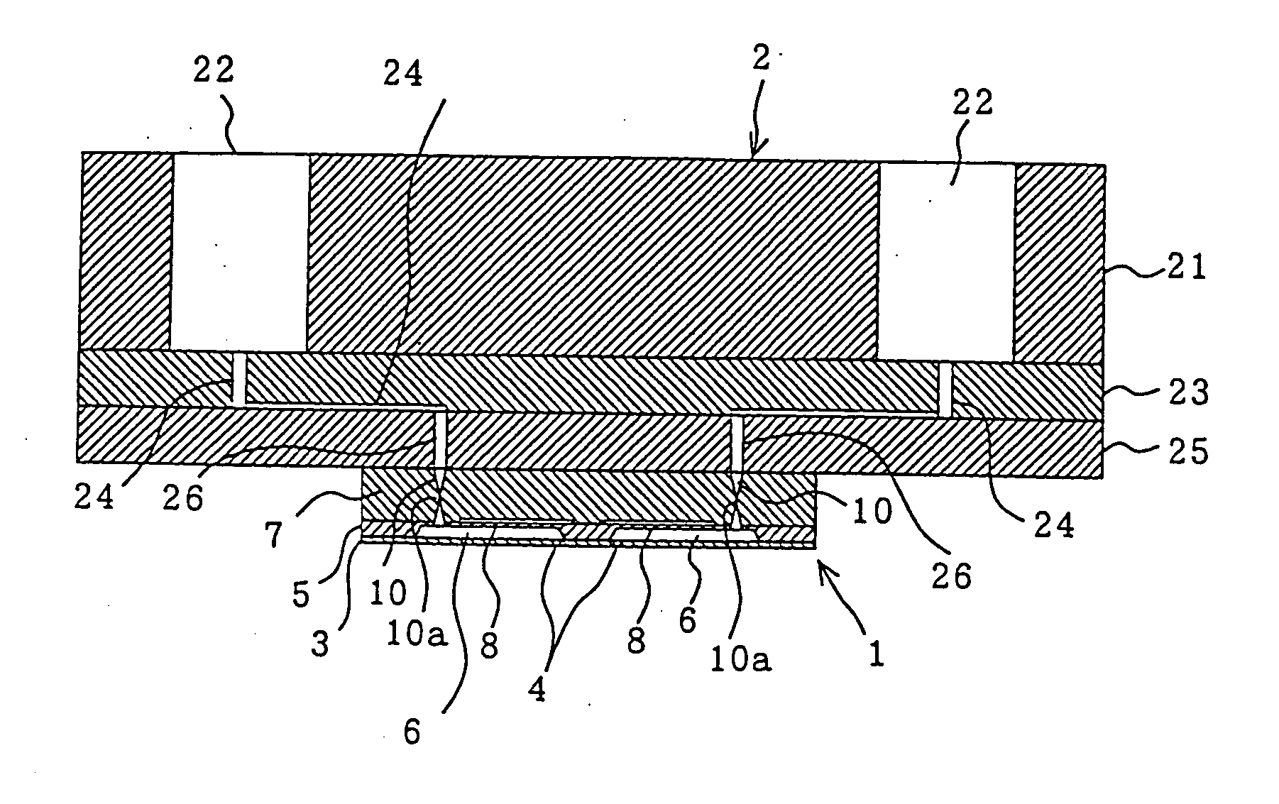
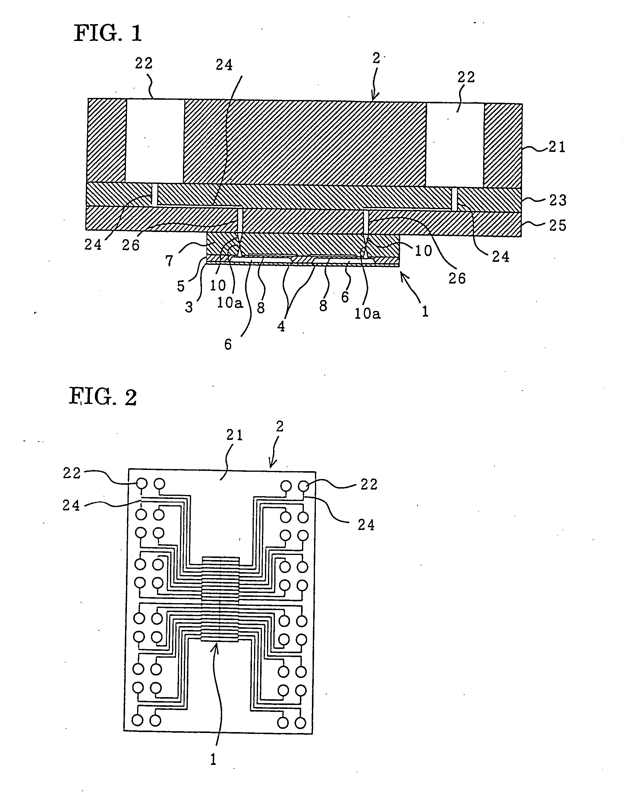
[0037]FIG. 1 is a cross-sectional view showing the structure of a liquid dispense head according to a first embodiment of the present invention; FIG. 2 is a structural view showing the liquid dispense head viewed from above: FIG. 3 is a cross-sectional view showing the structure of a head chip of the liquid dispense head; FIG. 4 is a cross-sectional view showing the structure of the head chip according to a first modified example; FIG. 5 is a cross-sectional view showing the structure of the head chip according to a second modified example; FIG. 6 is a structural view of the head chip according to the second modified example when it is viewed from above; and FIG. 7 is a cross-sectional view showing the structure of the head chip according to a third modified example.

[0038] In the figures, the liquid dispense head consists of a dispense head chip 1 for discharging many types of liquid droplets, for example, solutions containing biomolecules, and a reservoir unit 2 for supplying the ...

second embodiment

[0089]FIG. 9 is a cross-sectional view showing the structure of a liquid dispense head according to a second embodiment of the present invention.

[0090] In this second embodiment, a piezoelectric actuator is used instead of the electrostatic actuator described in the first embodiment, in order to dispense liquid droplets from the nozzle holes 4 with a pressure increased by warping the vibration plate 6a which is the bottom wall of the pressure chamber 6 provided in the second silicon substrate 5 of the dispense head chip 1.

[0091] The rest of the structure is the same as that in the first embodiment, and the same reference numerals designate the same constituent elements. Descriptions of the same structure, effect, and advantages are omitted.

[0092] In this second embodiment, a piezoelectric thin film 40 is formed on the surface of the bottom wall of the pressure chamber 6 of the second silicon substrate 5. This piezoelectric thin film 40 and the vibration plate 6a, that is, the bot...

third embodiment

[0096] In the above first and the second embodiments, in consideration of bonding between the second silicon substrate 5 and the glass substrate 7, which has the concave portions 8 and the minute through-holes 10 of the dispense head chip 1, by an anode bonding method, a borosilicate glass is used for the glass substrate 7. In this third embodiment, however, a photosensitive glass is used for the glass substrate 7, and the minute through-hole 10 is formed by irradiating the photosensitive glass with laser beams, followed by heat development and etching.

[0097] The photosensitive glass of this embodiment comprises a SiO2—Li2O—Al2O3-based glass as a primary component, a photosensitive metal (at least one of Au, Ag, and Cu), and a sensitizer (CeO2).

[0098] When this photosensitive glass is irradiated with laser beams, metal ions located at the irradiated part are turned into metal atoms, and by heat treatment performed at approximately 500 degree Celsius, metal colloids are formed. Sub...


PUM

PropertyMeasurementUnit
DC voltageaaaaaaaaaa
liquid dispenseaaaaaaaaaa
pressureaaaaaaaaaa

Abstract

A liquid dispense head is provided which can be manufactured at a reduced manufacturing cost, will not react with dispense liquid containing biomolecules, and can dispense liquid droplets having a constant amount from individual nozzles. The liquid dispense head has reservoirs used as reservoirs for containing liquid, pressure chambers for applying a pressure to dispense the liquid, flow passages connecting the pressure chambers and the respective reservoirs. In the liquid dispense head described above, a part of the flow passage is formed of a minute through-hole provided in a glass substrate, and the inside diameter of the minute through-hole is continuously decreased or increased.

Description

RELATED APPLICATIONS [0001] This application claims priority to Japanese Patent Application No. 2003-136808 filed May 15, 2003 which is hereby expressly incorporated by reference herein in its entirety. BACKGROUND OF THE INVENTION [0002] 1. Field of the Invention [0003] The present invention relates to liquid dispense heads and manufacturing methods thereof, the liquid dispense heads being used, for example, for fabricating a microarray by discharging a solution containing biomolecules such as proteins or nucleic acids onto a solid member. [0004] 2. Description of the Related Art [0005] Heretofore, when various types of probe samples are to be dispensed on a microarray substrate, a contact-pin method or an ink-jet method has been widely used. [0006] According to an ink-jet method, by decreasing pitches between nozzles, a high density microarray can be fabricated. [0007] In addition, in a conventional liquid dispense device, in order to supply liquid from reservoirs independent from ...

Claims


Application Information

Patent Timeline
Patent Type & Authority Applications(United States)
IPC IPC(8): B01L3/02B41J2/045B05C5/00B41J2/055B41J2/14B41J2/16C12M1/00C12N15/09G01N35/10
CPCB01L3/0268B01L2200/0684B41J2202/09B41J2/14016B41J2/14201B01L2400/0439
Inventor TAKAGI, FUMIOKUROSAWA, RYUICHISAWAKI, DAISUKE
Owner SEIKO EPSON CORP
Features
  • R&D
  • Intellectual Property
  • Life Sciences
  • Materials
  • Tech Scout
  • Unparalleled Data Quality
  • Higher Quality Content
  • 60% Fewer Hallucinations
Learn More