
Constant voltage generator and electronic equipment using the same

a constant voltage generator and electronic equipment technology, applied in the direction of electric generator control, dynamo-electric converter control, instruments, etc., can solve the problems of even more difficult application and difficulty in applying these constant voltage generators to about 1.3v of low power supply voltage, and achieve the effect of large current consumption

Inactive Publication Date: 2005-01-06
ROHM CO LTD
View PDF99 Cites 4 Cited by
  • Summary
  • Abstract
  • Description
  • Claims
  • Application Information

AI Technical Summary

Benefits of technology

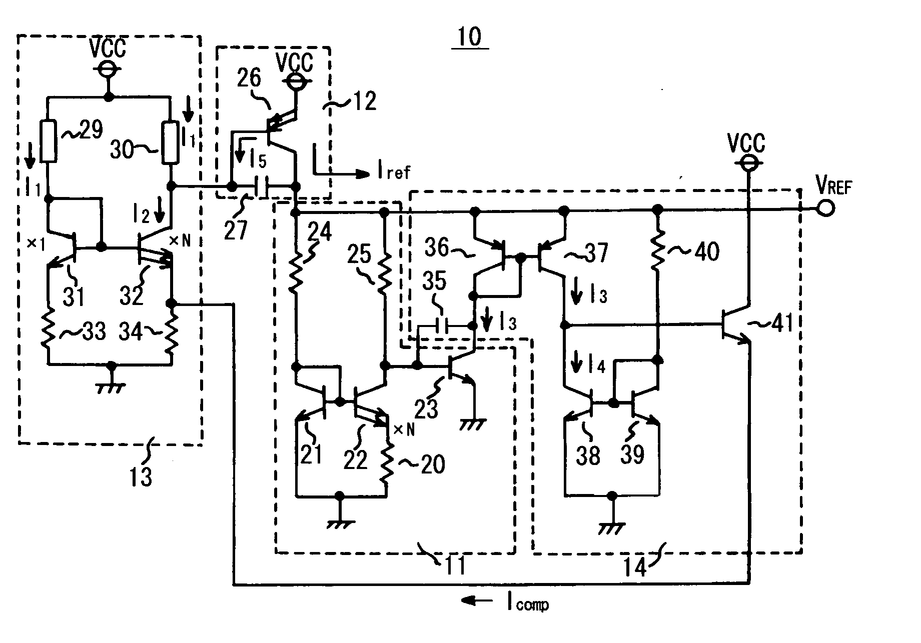
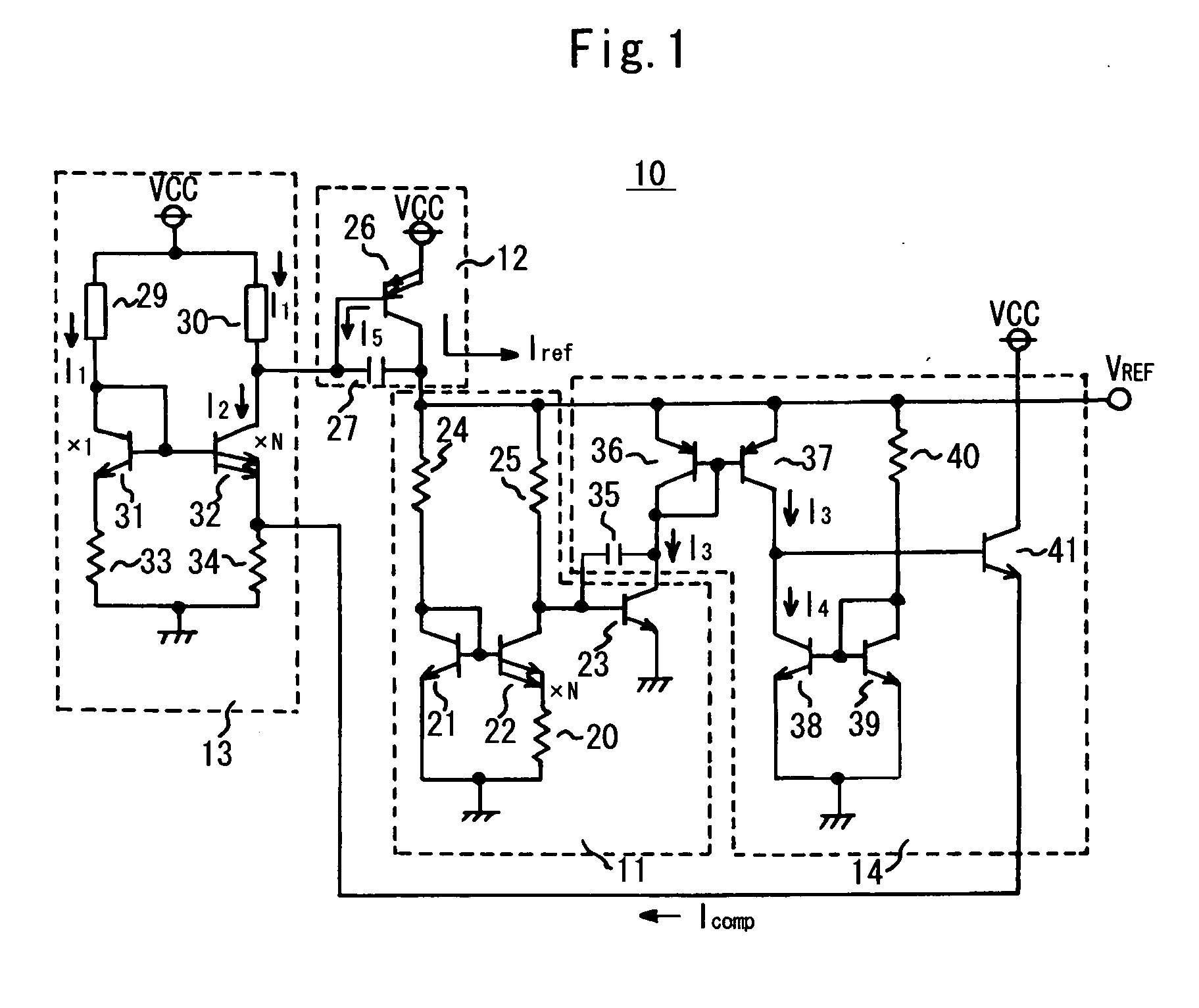
As described above, in the above-mentioned constant voltage generators 110 and 150, PNP transistors in a current mirror configuration are disposed in the current supply circuits 112 or 152, and stable current is supplied to the output (VREF) by controlling the input of this current mirror configuration. In the constant voltage generators 110 and 150, the starting circuit 113 or 153 which has two stages of diodes is disposed, but once the band gap reference circuit 111 or 151 is started, the influence of the starting circuit 113 or 153 on the constant voltage generators 110 and 150 is prevented.
According to the present invention, a constant voltage generator that can operate even if the power supply voltage (VCC) is low, such as 1.3V, and can output current according to the load of the output terminal (VREF), and can output 1 mA or more of current without consuming unnecessary current can be provided, and electronic equipment that can operate even if the power supply voltage (VCC) is low and the large current is consumed can be achieved.

Problems solved by technology

However these constant voltage generators 110 and 150 are not intended to operate with a low power supply voltage (VCC), and it is difficult to apply these constant voltage generators to about 1.3V of low power supply voltage (VCC).
Also this forward bias voltage (Vf) normally increases as the temperature decreases, so if the temperature environment is considered, this application is even more difficult.
Recently demands for lower voltage for the power supply voltage (VCC) of constant voltage generators is becoming stronger not only for portable electronic equipment but also for stationary type electronic equipment, this is due to low power consumption issues.

Method used


Image

  • Constant voltage generator and electronic equipment using the same
  • Constant voltage generator and electronic equipment using the same
  • Constant voltage generator and electronic equipment using the same

Examples


fourth embodiment

Now the constant voltage generator according to the present invention will be described. In this embodiment, only the starting circuit is different from the previous three embodiments, and FIG. 4 is a circuit diagram of this starting circuit.

The starting circuit 90 is comprised of transistors 93 and 98 which constitute the constant current source by the current mirror configuration, a transistor 94 which shares the voltage of the base, that is the control terminal, with these transistors 93 and 98, and of which emitter-base area is N times (current capability is N times), resistors 95, 96 and 99 of which the resistance values are the same, a third load element 97 which is a constant current supply or resistor, and transistors 91 and 92 which are the first and second load elements and constitute the current mirror circuit. The group consisted of the third load element 97, transistor 98 and resistor 99, the group consisted of the transistors 91 and 93 and resistor 95, and the group c...


PUM


Abstract

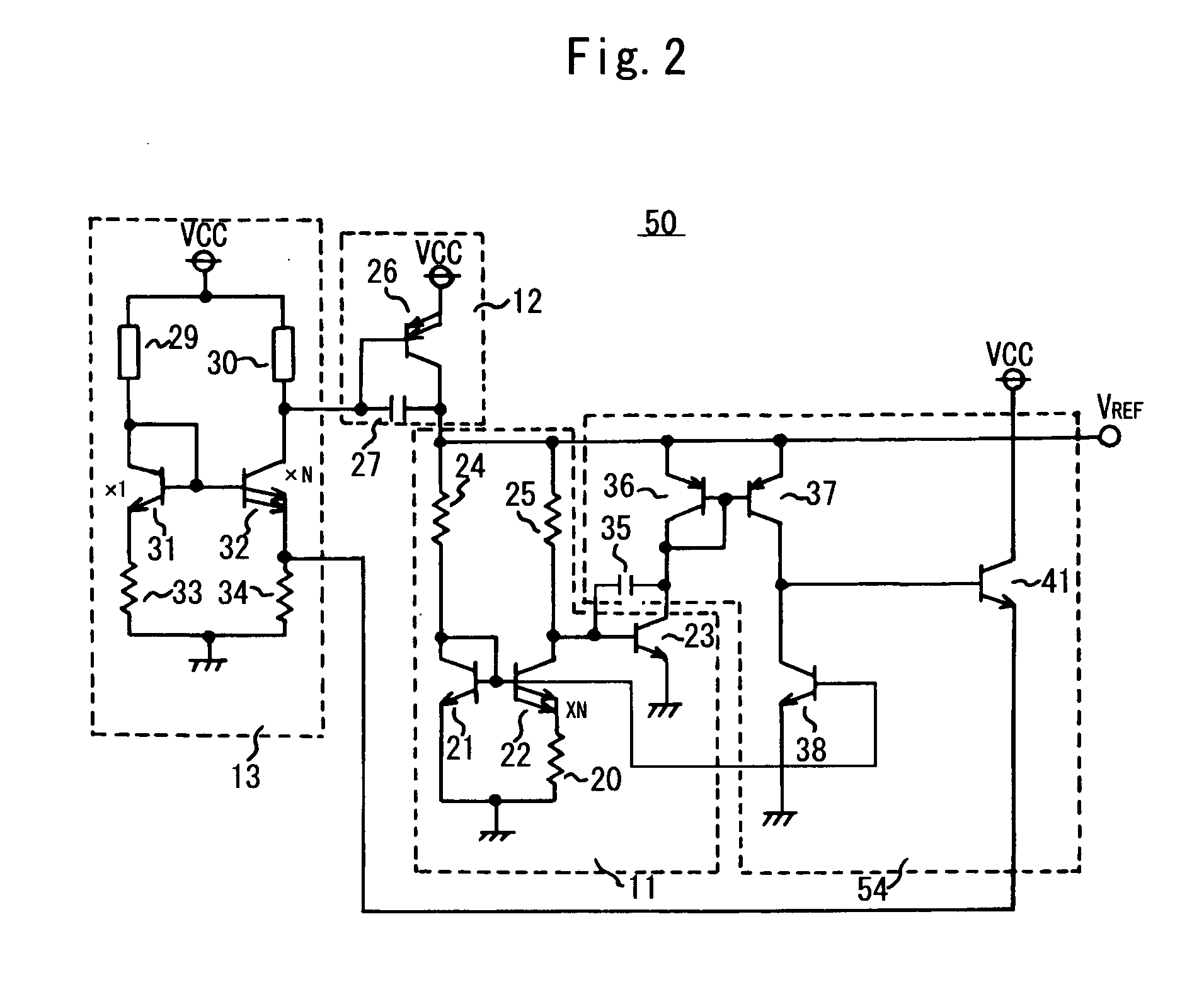
A constant voltage generator is comprised of a band gap reference circuit, a current supply circuit, a starting circuit and a voltage-current conversion circuit, and the starting circuit is further comprised of a first and second load elements, a first transistor which is connected to the first load element, a second transistor of which current capability is larger than the first transistor and which shares the voltage of the base with the first transistor and is connected to the second load element, a first resistor which is connected to the first transistor, and a second resistor which is connected to the second transistor, and the output of the voltage-current conversion circuit is input to the connection point between the second transistor and the second resistor, and the current at the connection point between the second load element and the second transistor controls the current supply circuit.

Description

BACKGROUND OF THE INVENTION 1. Field of the Invention The present invention relates to a constant voltage generator for outputting constant voltage, and more particularly to a constant voltage generator comprising an improved starting circuit, and relates to electronic equipment using such a constant voltage generator. 2. Description of the Related Art A constant voltage generator is widely used for electronic circuits for securing the accuracy of an analog circuit or decreasing the power consumption of a circuit. One type of constant voltage generator is one using a band gap reference circuit (e.g. Japanese Patent Application Laid-Open No. H3-164916, Japanese Patent Application Laid-Open No. H7-230332). A band gap reference circuit is constructed by combining matched transistors on a semiconductor integrated circuit, and the advantage is that it does not depend on temperature. A constant voltage generator using a band gap reference circuit requires a transistor for supplying c...

Claims


Application Information

Patent Timeline
Patent Type & Authority Applications(United States)
IPC IPC(8): G05F3/22G05F3/30
CPCG05F3/222Y10S323/901G05F3/30G05F3/22
Inventor NAKATA, KENICHI
Owner ROHM CO LTD
Learn More