Optical device and projector

Inactive Publication Date: 2005-01-06
SEIKO EPSON CORP
View PDF2 Cites 35 Cited by
  • Summary
  • Abstract
  • Description
  • Claims
  • Application Information

AI Technical Summary

Benefits of technology

[0055] According to the present invention, since the projector has the above-described optical device, the same functions and advantages as the above-described optical device can be obtained.
[0056] Also, since the projector includes the low-cost optical device, the production cost of the projector can be reduced.
[0057] Further, since the projector includes the optical device having a good cooling efficiency, it

Problems solved by technology

According to the invention disclosed in Patent Document 1, however, since the polarization plate arranged on the downstream of the optical modulator is directly attached to the light-incident face of the cross dichroic prism, it is difficult that the

Method used


Image

  • Optical device and projector
  • Optical device and projector
  • Optical device and projector

Examples


first embodiment

[0073] [First Embodiment]

[0074] A first embodiment of the present invention will be described below with reference to the attached drawings.

[0075] [1] Structure of Projector

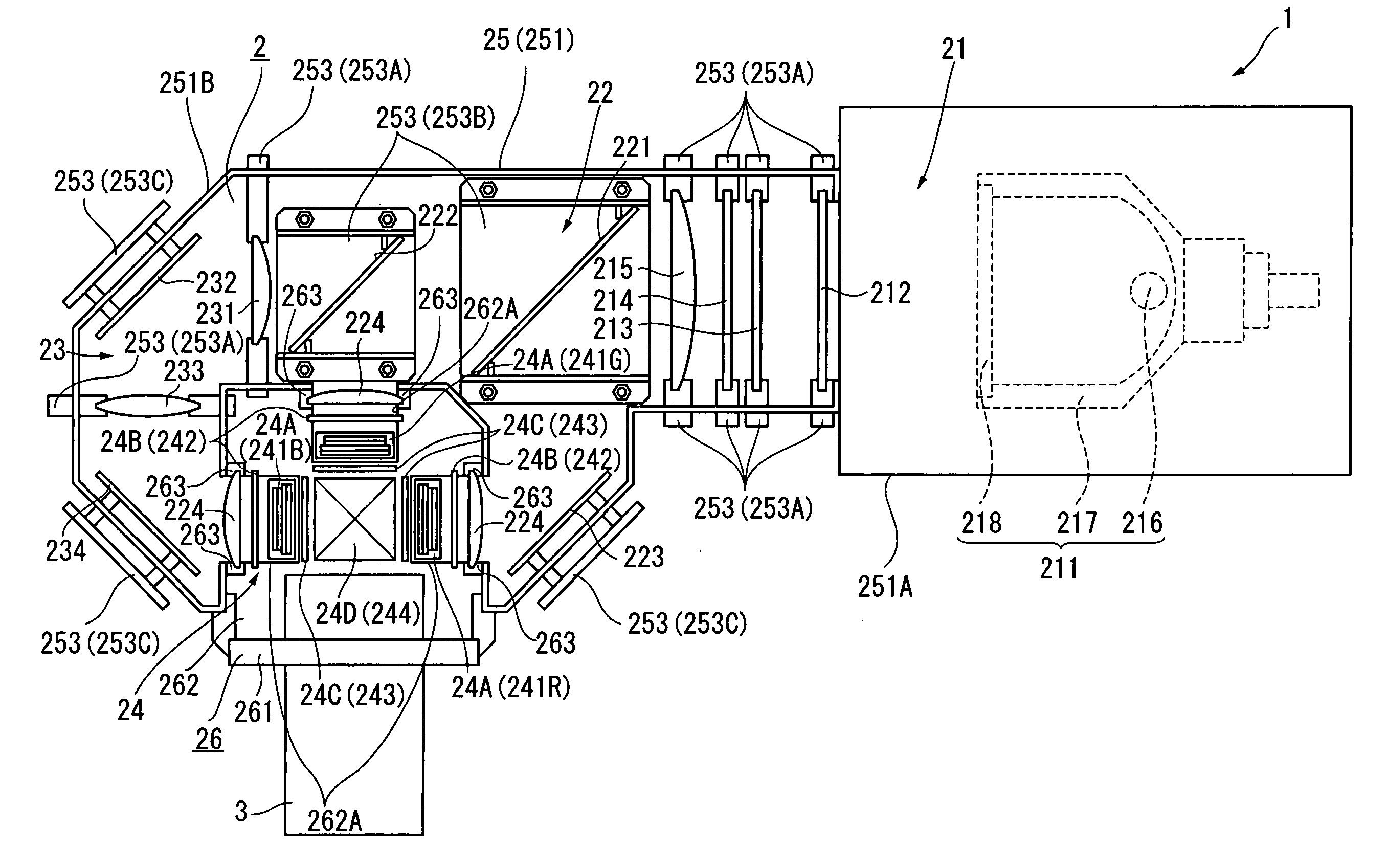
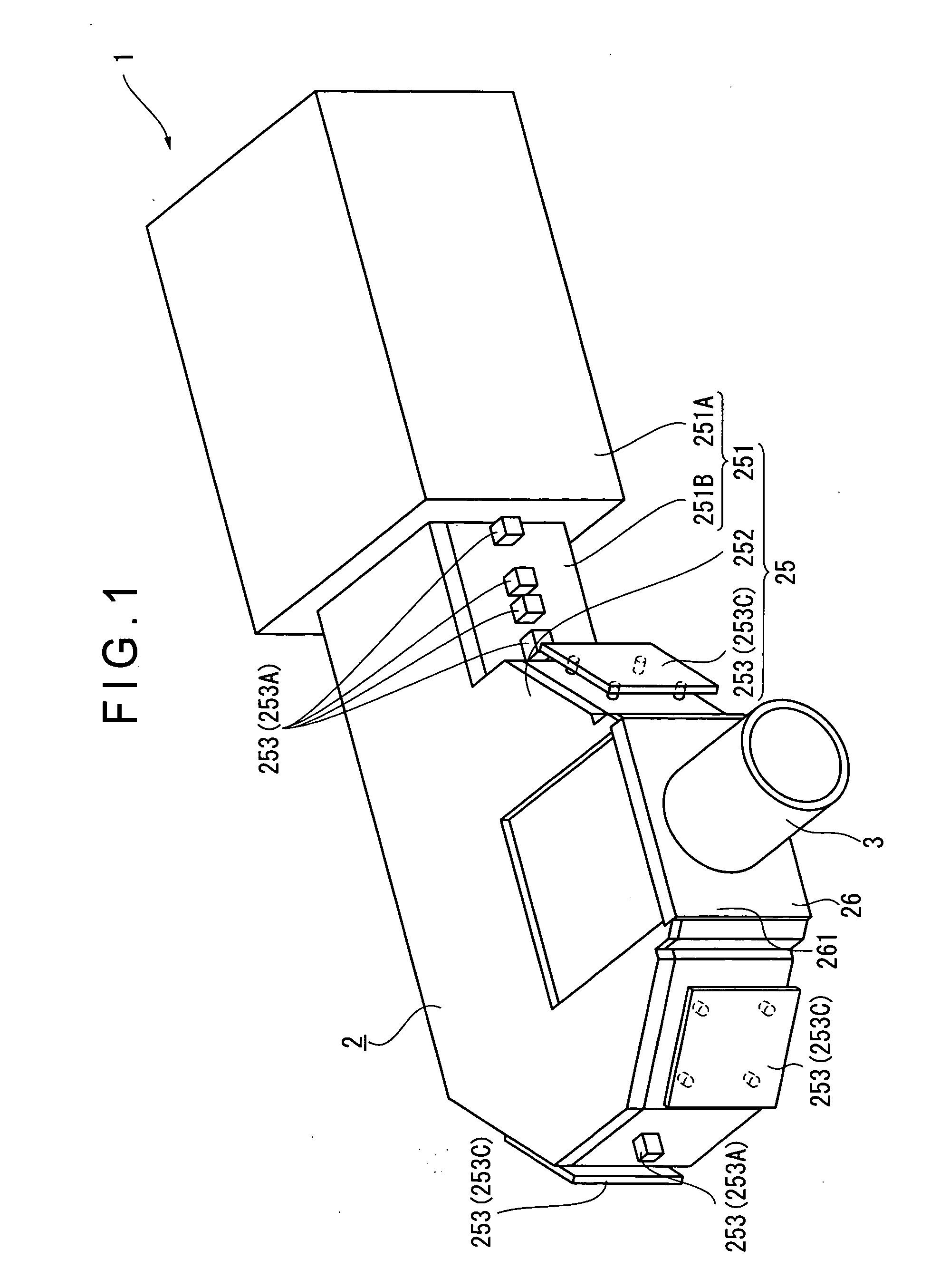
[0076]FIG. 1 is a perspective view showing a structure of a projector 1 having an optical device according to a present embodiment.

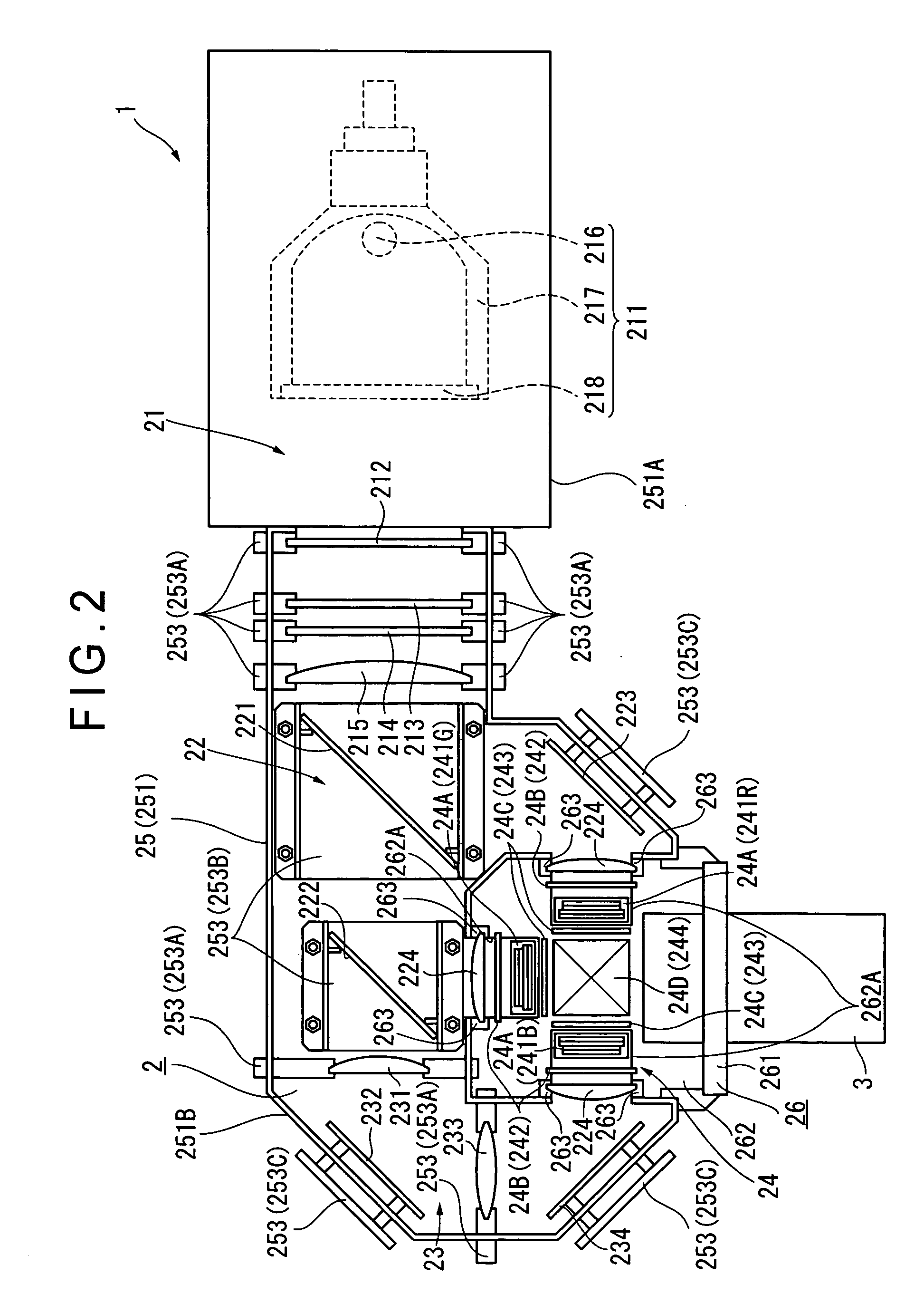
[0077] The projector 1 modulates a light beam irradiated from a light source in accordance with image information and projects the light beam on a projection surface of a screen or the like in an enlarged manner. The projector 1, as shown in FIG. 1, has an optical unit 2 having a substantially L-shape in plan view and a projection lens 3 as a projection optical device connected to an end of the optical unit 2.

[0078] Though not particularly shown, the projector 1 includes a power source unit for providing electric power supplied from the outside to the components of the projector 1, a control board for controllably driving a below-described liquid crystal panel of the optical unit ...

second embodiment

[0239] [Second Embodiment]

[0240] Next, a second embodiment of the present invention will be described.

[0241]FIG. 13 is an illustration showing an irradiation-side polarization unit 34C according to the second embodiment.

[0242] In the following description, the components same as those in the first embodiment are indicated by the same reference symbols or numerals for omitting or simplifying the detailed description thereof.

[0243] According to the first embodiment, in the irradiation-side polarization unit 24C, the plate member 246A of the irradiation-side retaining plate 246 is so formed that the bonding portions 246A2 and the support portion 246A4 are flush with each other.

[0244] In contrast, according to the second embodiment, in the irradiation-side polarization unit 34C, a plate member 346A of an irradiation-side retaining plate 346 is so bent to have three areas in the vertical direction as shown in FIG. 13. Specifically, upper and lower areas serve as bonding portions 346A...

third embodiment

[0248] [Third Embodiment]

[0249] Next, a third embodiment of the present invention will be described.

[0250]FIG. 14 is an illustration showing an irradiation-side polarization unit 44C according to the third embodiment.

[0251] In the following description, the components same as those in the first embodiment are indicated by the same reference symbols or numerals for omitting or simplifying the detailed description thereof.

[0252] According to the first embodiment, in the irradiation-side polarization unit 24C, the plate member 246A of the irradiation-side retaining plate 246 is so formed that the bonding portions 246A2 and the support portion 246A4 are flush with each other. The protrusions 246B of the irradiation-side retaining plate 246 protrude from the plate member 246A toward the light-irradiation side.

[0253] In contrast, according to the third embodiment, in the irradiation-side polarization unit 44C, a plate member 446A of an irradiation-side retaining plate 446 is so bent t...


PUM


Abstract

An optical device (24) includes: three optical modulators (24A) for modulating respective color lights in accordance with image information; a cross dichroic prism (244) for combining the respective color lights modulated by the optical modulators (24A); a base (247) made of heat-conductive material and fixed to upper and lower faces of the cross dichroic prism (244); an irradiation-side polarization plate (243) having polarization films (243A2 and 243B2) as optical conversion films for converting an optical property of a light beam irradiated by the optical modulators (24A) and substrates (243A1 and 243B1) made of heat-conductive material and provided with the polarization films (243A2 and 243B2) attached thereto; and an irradiation-side retaining plate (246) made of heat-conductive material for supporting and fixing the irradiation-side polarization plate (243). The irradiation-side retaining plate (246) is fixed to a lateral face of the base (247).

Description

BACKGROUND OF THE INVENTION [0001] 1. Field of the Invention [0002] The present invention relates to an optical device and a projector. [0003] 2. Description of Related Art [0004] There has been known a three-plate projector having a color-separating optical system that separates a light beam irradiated by a light source into three color lights, three optical modulators that modulate the respective color lights in accordance with image information, a cross dichroic prism that combines the light beams modulated by the respective optical modulators (refer to, for example, Patent Document 1: Japanese Patent Laid-Open Publication No. 2000-221588, FIG. 5). [0005] A polarization plate (optical conversion plate) that transmits only a light beam along a direction of a polarization axis out of the incident light beams and absorbs light beams along other directions so as to irradiate a predetermined polarized light is arranged on each of the incident side and the irradiation side of the optic...

Claims


Application Information

Patent Timeline
IPC IPC(8): G02B7/00G02F1/13G03B21/00G03B21/14G03B21/16H04N9/31
CPCG03B21/14H04N9/3197H04N9/3144G03B21/16G03B21/145
Inventor KITABAYASHI, MASASHI
Owner SEIKO EPSON CORP
Why Eureka
Try Eureka