Illuminating system having a diffuser element

a diffuser element and illumination system technology, applied in the field of illumination systems, can solve the problems of inability to always implement structurally and appropriate outlay, and achieve the effect of low outlay and little installation spa

Inactive Publication Date: 2005-01-06
CARL ZEISS SMT GMBH
View PDF24 Cites 19 Cited by
  • Summary
  • Abstract
  • Description
  • Claims
  • Application Information

AI Technical Summary

Benefits of technology

[0010] One object on which the invention is based is to provide an illuminating system of the type mentioned above, which can be implemented and operated with a comparatively low outlay, requires little installation space and does not significantly disturb other system components possibly present in the surroundings, and which is therefore also particularly suitable for microlithography projection exposure machines and associated wavefront measurement interferometers.

Problems solved by technology

Although an interferometer calibration in which the measured projection objective is rotated about the optical axis does come into consideration as a possible measure of achieving the required measuring accuracy, this requires an appropriate outlay, and cannot always be implemented structurally.

Method used


Image

  • Illuminating system having a diffuser element
  • Illuminating system having a diffuser element
  • Illuminating system having a diffuser element

Examples


Embodiment Construction

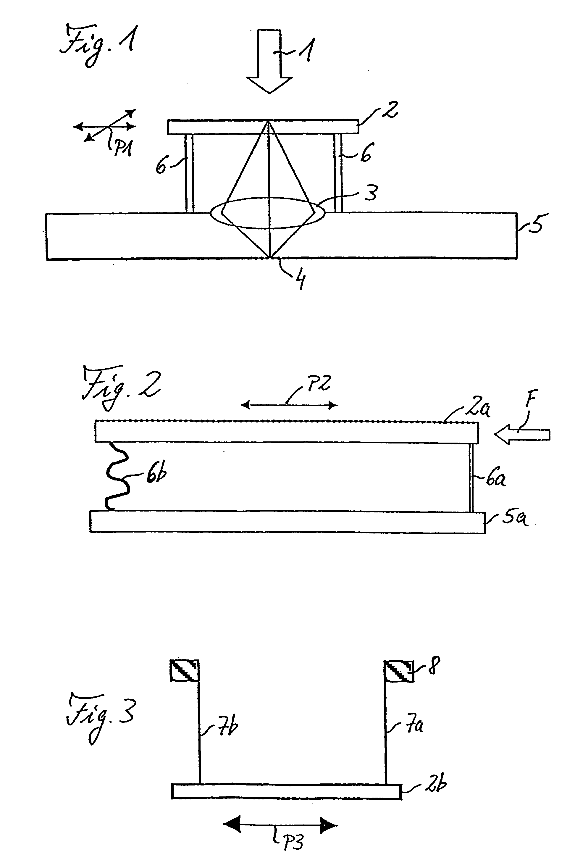
[0033]FIG. 1 shows a schematic of the part, presently of interest, of an illuminating system such as can be used in a microlithography projection exposure machine and in an associated interferometer for the purpose of wavefront measurement of a projection objective of the projection exposure machine. Positioned downstream of the illuminating system part shown is a laser light source (not shown) that emits, for example, UV light with a wavelength of 193 nm or some other wavelength.

[0034] The illuminating system part shown includes a diffuser plate 2 that is introduced into an illuminating beam path 1 of the system and is typically in the form of a ground glass screen downstream of which is a focusing optical system 3 that focuses the illuminating radiation passed by the diffuser plate 2 on to a mask structure 4. In the usual way, the mask structure 4 can be, for example, a chromium mask, and is mounted on the underside of a reticle 5 on the top side of which the focusing optical sys...


PUM

PropertyMeasurementUnit
wavelengthaaaaaaaaaa
pressureaaaaaaaaaa
gas pressureaaaaaaaaaa

Abstract

An illuminating system having a diffuser element (2) that is introduced into an illuminating beam path (1) and is arranged movably, in particular for oscillatory movement. Such system has applicability, for example, in microlithography projection exposure machines and associated wavefront measurement interferometers.

Description

[0001] The following disclosure is based on German Patent Application No. 103 20 520.9, filed on Apr. 30, 2003, which is incorporated into this application by reference. BACKGROUND OF THE INVENTION [0002] 1. Field of the Invention [0003] The invention relates generally to an illuminating system. More particularly, the invention relates to an illuminating system having a diffuser element that is introduced into an illuminating beam path and arranged movably. [0004] 2. Description of the Related Art [0005] Illuminating systems of this type are known in different designs. The mobility of the diffuser element normally serves in this case principally for reducing the spatial coherence of the illuminating radiation used. This is useful for various applications. [0006] Thus, U.S. Pat. No. 6,061,133 discloses the use of a movable diffuser element in an interferometer, for example of the Fizeau type, Twyman-Green type or Mach-Zehnder type. The diffuser element is formed there from a circular...

Claims


Application Information

Patent Timeline
Patent Type & Authority Applications(United States)
IPC IPC(8): G02B5/02G03F7/20
CPCG02B5/02G03F7/70075G02B27/48
Inventor WEGMANN, ULRICHTRAUTWEIN, FRANZ
Owner CARL ZEISS SMT GMBH
Why Eureka
Try Eureka