

Interference and noise estimation in an OFDM system
a technology of interference and noise estimation, applied in the field of wireless communications, can solve the problems of affecting the number of sub-carriers assigned to a particular user over time, limiting the frequency spectrum or bandwidth that is allocated to a communication system, and affecting the efficiency of data throughput optimization
- Summary
- Abstract
- Description
- Claims
- Application Information
AI Technical Summary
Benefits of technology
Problems solved by technology
Method used
Image

Examples
Embodiment Construction
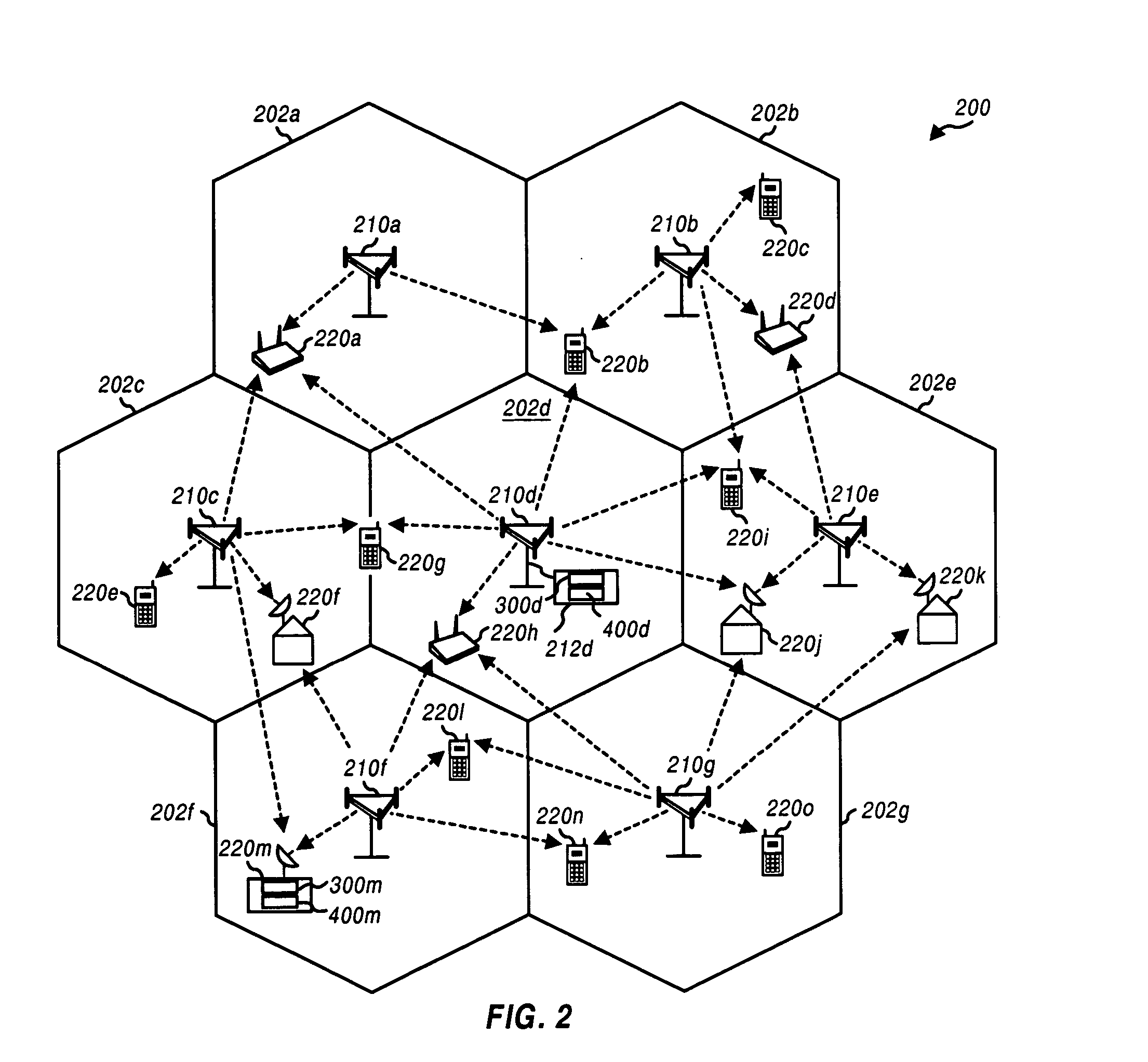
[0024] A functional block diagram of a cellular OFDM wireless communication system 200 having receivers that incorporate sub-carrier noise and interference detection is shown in FIG. 2. The OFDM system 200 includes a number of base stations 210a-210g that provide communication for a number of terminals 220a-220o. A base station, for example 210a, can be a fixed station used for communicating with the terminals, for example 220a, and may also be referred to as an access point, a Node B, or some other terminology.
[0025] Various terminals 220a-220o may be dispersed throughout the OFDM system 200, and each terminal may be fixed, for example 220k, or mobile, for example 220b. A terminal, for example 220a may also be referred to as a mobile station, a remote station, a user equipment (UE), an access terminal, or some other terminology. Each terminal, for example 220a, may communicate with one or possibly multiple base stations on the downlink and / or uplink at any given moment. Each termi...
PUM
 Abstract
Description
Claims
Application Information