
Switch module memory structure and per-destination queue flow control for use in a switch

a switch module and memory structure technology, applied in the field of communication, can solve the problems of high cost and complexity of building such a large-capacity router, significantly affecting the power consumption and cost of interconnection technology, and reducing so as to reduce the bandwidth of cell headers and improve performance. the effect of memory space and improved performan

Active Publication Date: 2005-01-06
POLYTECHNIC INST OF NEW YORK
View PDF61 Cites 71 Cited by
  • Summary
  • Abstract
  • Description
  • Claims
  • Application Information

AI Technical Summary

Benefits of technology

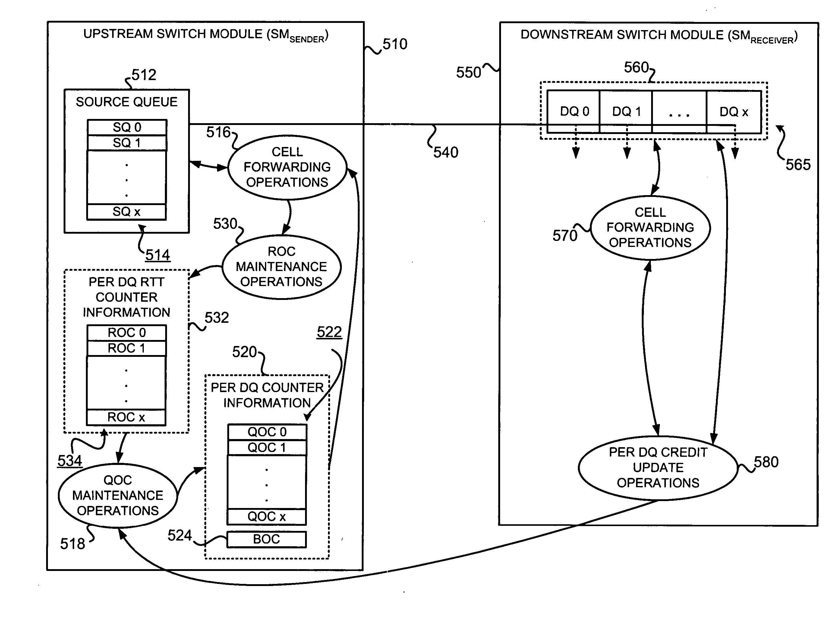
To use the memory space more effectively, the present invention may allow cell memory to be shared by an input link and all output links. To prevent one flow from occupying the entire memory space, the present invention may set a threshold for the queue. The queue threshold may accommodate the RTT delay of the link.

Problems solved by technology

It still remains a challenge to build a very large IP router with a capacity of tens Tbps or more.
The complexity and cost of building such a large-capacity router is much higher than building an optical cross connect system (OXC).
Memory technology very often becomes a bottleneck of a packet switch system.
Interconnection technology significantly affects a system's power consumption and cost.
As a result, designing a good switch architecture that is both scalable to handle a very large capacity and cost-effective remains a challenge.
The numbers of switch elements and interconnections are often critical to the switch's scalability and cost.
Since the number of switch elements of single-stage switches is proportional to the square of the number of switch ports, single-stage architecture is not attractive for large switches.
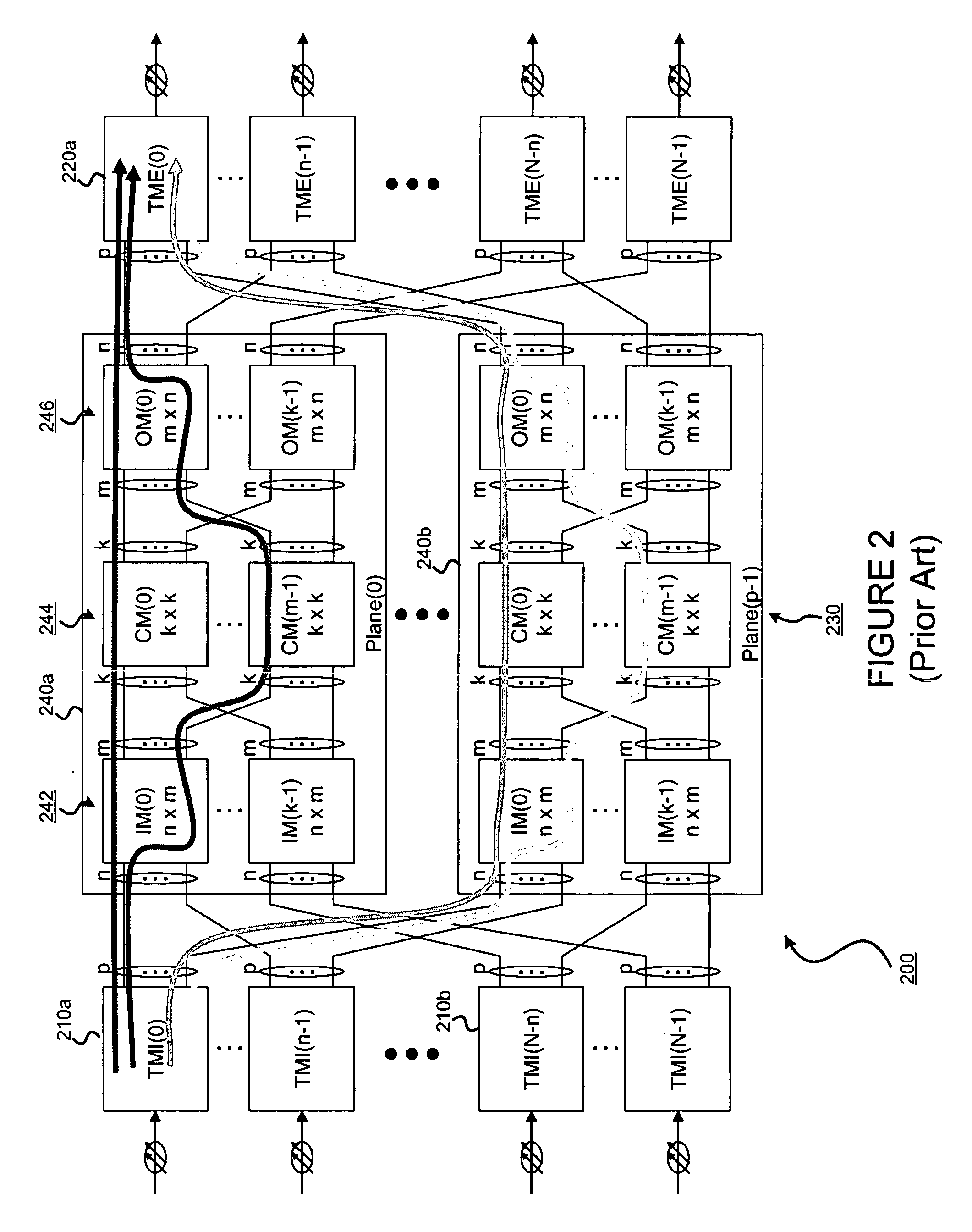
These different delays may result in cells arriving at a TME 220 out of sequence.
Such issues may include buffering in (switch modules of) the switch fabric and flow control.
The complexity of the global coordination can be very high and the arbitration time for such global coordination can be quite long.
Accordingly, a switch fabric with memory-less SMs might not be feasible for a large scale, high-speed switch.
The memory size in the SM affects system performance.
However, memory size is limited by VLSI technology.
However, queues in different buffers do not share memory space.
Such communication between senders makes the implementation difficult.
A second problem is ensuring that the queues don't overflow, which may require some sort of flow control.
This can lead to a deadlock situation.
Although the senders may coordinate with each other to prevent buffer overflow, a deadlock situation can still occur.
This can cause a deadlock under a packet interleaving scheme, such as the one described in the '733 provisional.
As can be appreciated from the foregoing, one of the challenges in building a large capacity switch is to use memory efficiently.
Unfortunately, the N23 scheme discussed in the Kung paper will not work with a multi-plane, multi-stage, packet switch because the number of VCs can be too big to be practical.
This may consume a significant portion of the link bandwidth.
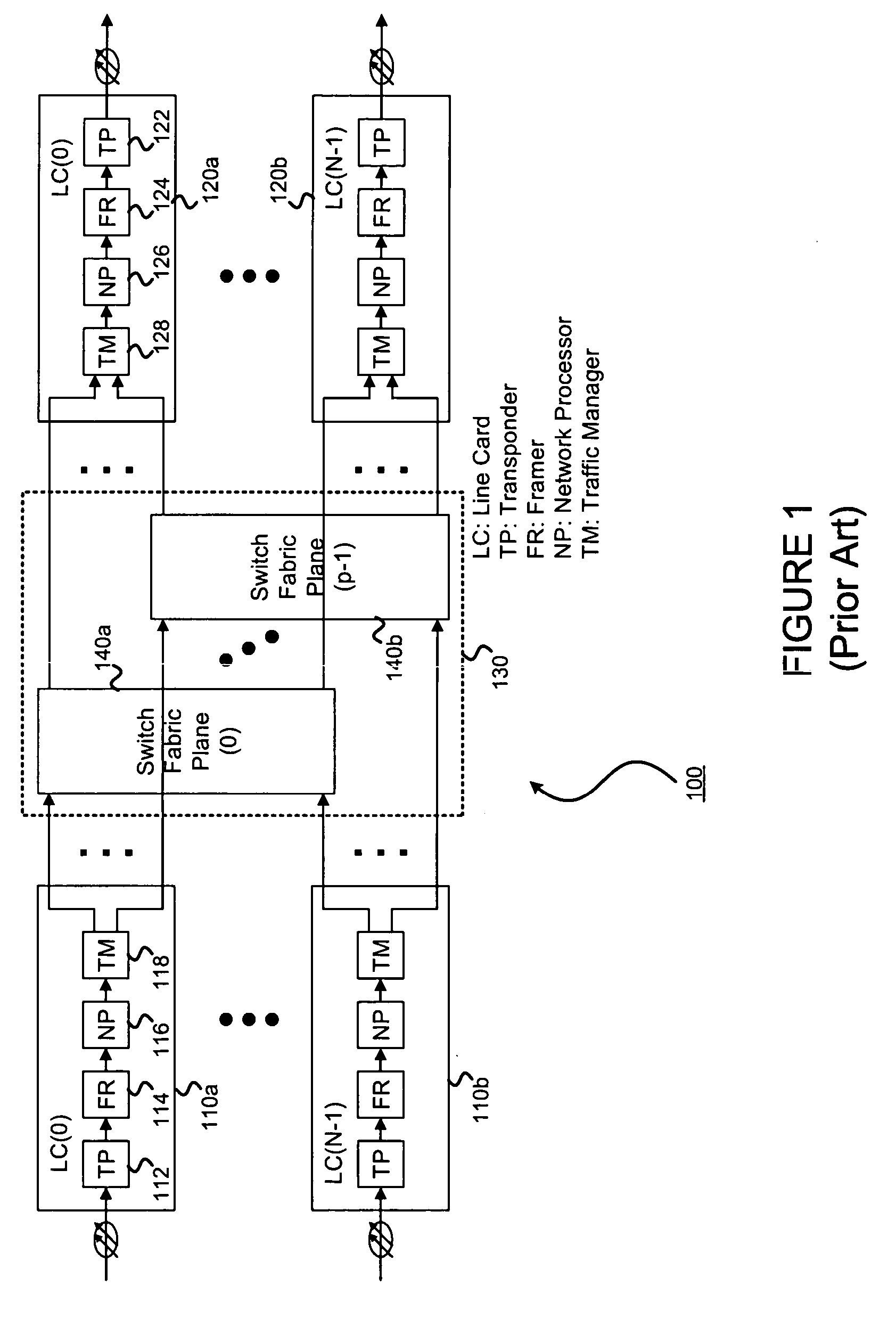
However, large-scale, high-speed, switches often use a multi-plane, multi-stage architecture.

Method used


Image

  • Switch module memory structure and per-destination queue flow control for use in a switch
  • Switch module memory structure and per-destination queue flow control for use in a switch
  • Switch module memory structure and per-destination queue flow control for use in a switch

Examples


Embodiment Construction

The present invention may involve novel methods, apparatus, message formats and / or data structures for providing efficient buffering at an SM, and may provide flow control. The following description is presented to enable one skilled in the art to make and use the invention, and is provided in the context of particular applications and their requirements. Various modifications to the disclosed embodiments will be apparent to those skilled in the art, and the general principles set forth below may be applied to other embodiments and applications. Thus, the present invention is not intended to be limited to the embodiments shown and the inventors regard their invention as any patentable subject matter described.

In the following, abbreviations and letter symbols used in the specification are introduced in § 4.1. Then, exemplary embodiments of the present invention are described in § 4.2. Finally, some conclusions are set forth in § 4.3.

§ 4.1 Abbreviations

The following letter symb...


PUM


Abstract

To use the memory space more effectively, cell memory can be shared by an input link and all output links. To prevent one flow from occupying the entire memory space, a threshold may be provided for the queue. The queue threshold may accommodate the RTT delay of the link. Queue length information about a downstream switch module may be sent to an upstream switch module via cell headers in every credit update period per link. Cell and / or credit loss may be recovered from. Increasing the credit update period reduces the cell header bandwidth but doesn't degrade performance significantly. Sending a credit per link simplifies implementation and eliminates interference between other links.

Description

§ 1. BACKGROUND OF THE INVENTION 1. Field of the Invention The present invention concerns communications. In particular, the present invention concerns structures of switch module cell memory, and preventing cell memory overflow in large scale switches used in communications networks. 2. Related Art To keep pace with Internet traffic growth, researchers continually explore transmission and switching technologies. For instance, it has been demonstrated that hundreds of signals can be multiplexed onto a single fiber with a total transmission capacity of over 3 Tbps and an optical cross-connect system (OXC) can have a total switching capacity of over 2 Pbps. However, the capacity of today's (Year 2003) core Internet Protocol (IP) routers remains at a few hundred Gbps, or a couple Tbps in the near future. It still remains a challenge to build a very large IP router with a capacity of tens Tbps or more. The complexity and cost of building such a large-capacity router is much higher ...

Claims


Application Information

Patent Timeline
Patent Type & Authority Applications(United States)
IPC IPC(8): H04L12/28
CPCH04L49/506H04L49/1523
Inventor CHAO, HUNG-HSIANG JONATHANPARK, JINSOO
Owner POLYTECHNIC INST OF NEW YORK
Learn More