Method and apparatus for automatic tuning of a resonant loop antenna in a transceiver circuit

a transceiver circuit and automatic tuning technology, applied in the field of transceiver circuits, can solve the problems of circuit failure, high minimum limit of supply voltage and signal amplitude on the antenna, and disrupt oscillation, and achieve low operating voltage supply levels and high output signal levels

Inactive Publication Date: 2005-01-06
SILICON LAB INC
View PDF18 Cites 44 Cited by
  • Summary
  • Abstract
  • Description
  • Claims
  • Application Information

AI Technical Summary

Problems solved by technology

However, since continuous tuning is necessary for the PLL, only varactors can be used, which require higher voltage levels that place a relatively high minimum limit on the supply voltage and the signal amplitude on the antenna.
Further, any mistuning effects that may occur due to the antenna may cause the oscillator to fall out of the tuning range of the PLL thereby disrupting oscillation and causing the circuit to cease functioning.
The method of Gaskill et al., however, the antenna tuning approach lacks an adaptive capability with respect to changes in the device environment or in component selection.
Further, overall system requirements typically impose certain time limitations on the time available for the antenna tuning procedure, which therefore impose limitations on the accuracy of the antenna tuning procedure as set forth under the Gaskill method.
This solution has a limited accuracy due to the reduced number of capacitance cells and cannot follow changes in conditions that may occur during long transmission periods.

Method used


Image

  • Method and apparatus for automatic tuning of a resonant loop antenna in a transceiver circuit
  • Method and apparatus for automatic tuning of a resonant loop antenna in a transceiver circuit
  • Method and apparatus for automatic tuning of a resonant loop antenna in a transceiver circuit

Examples


Embodiment Construction

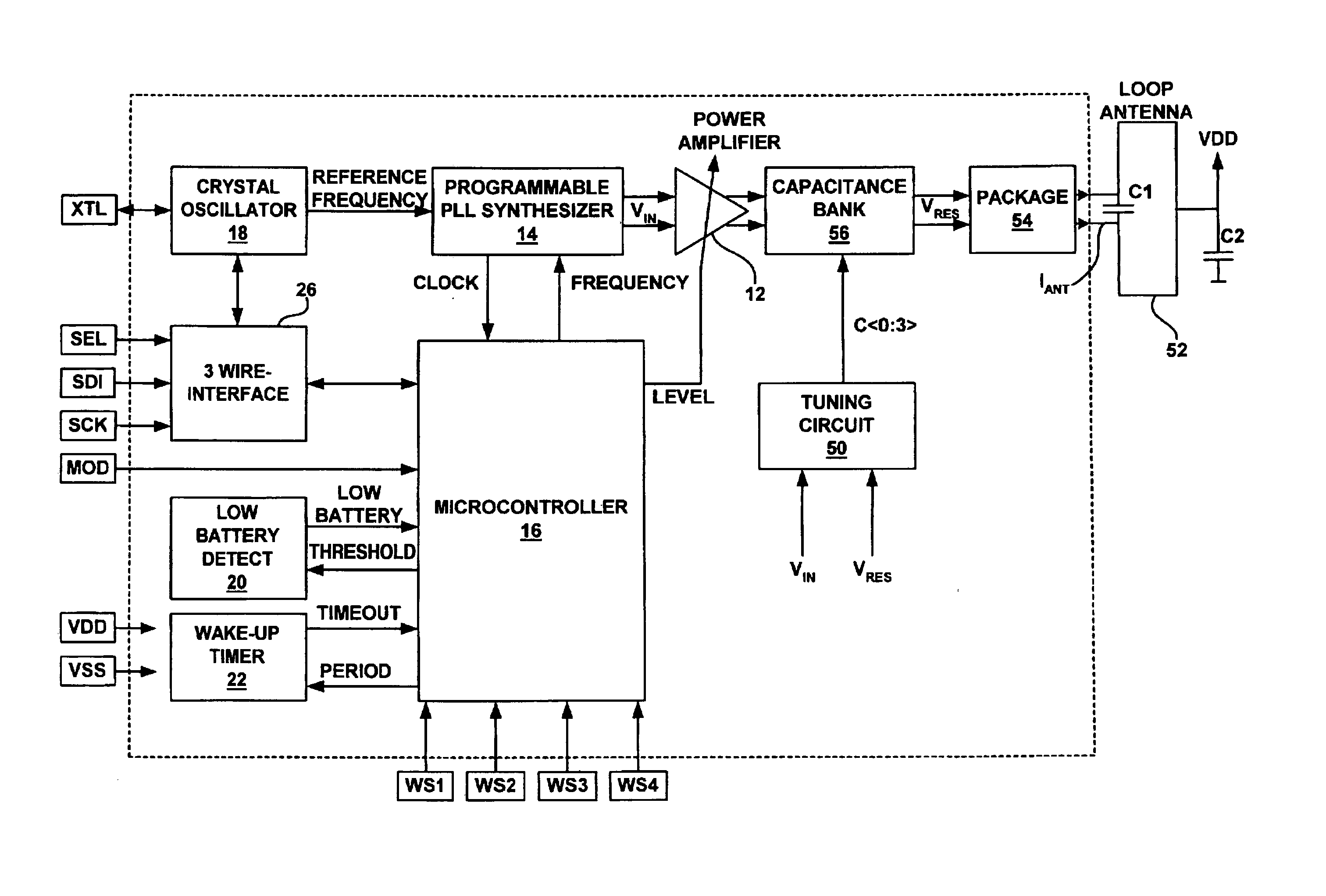
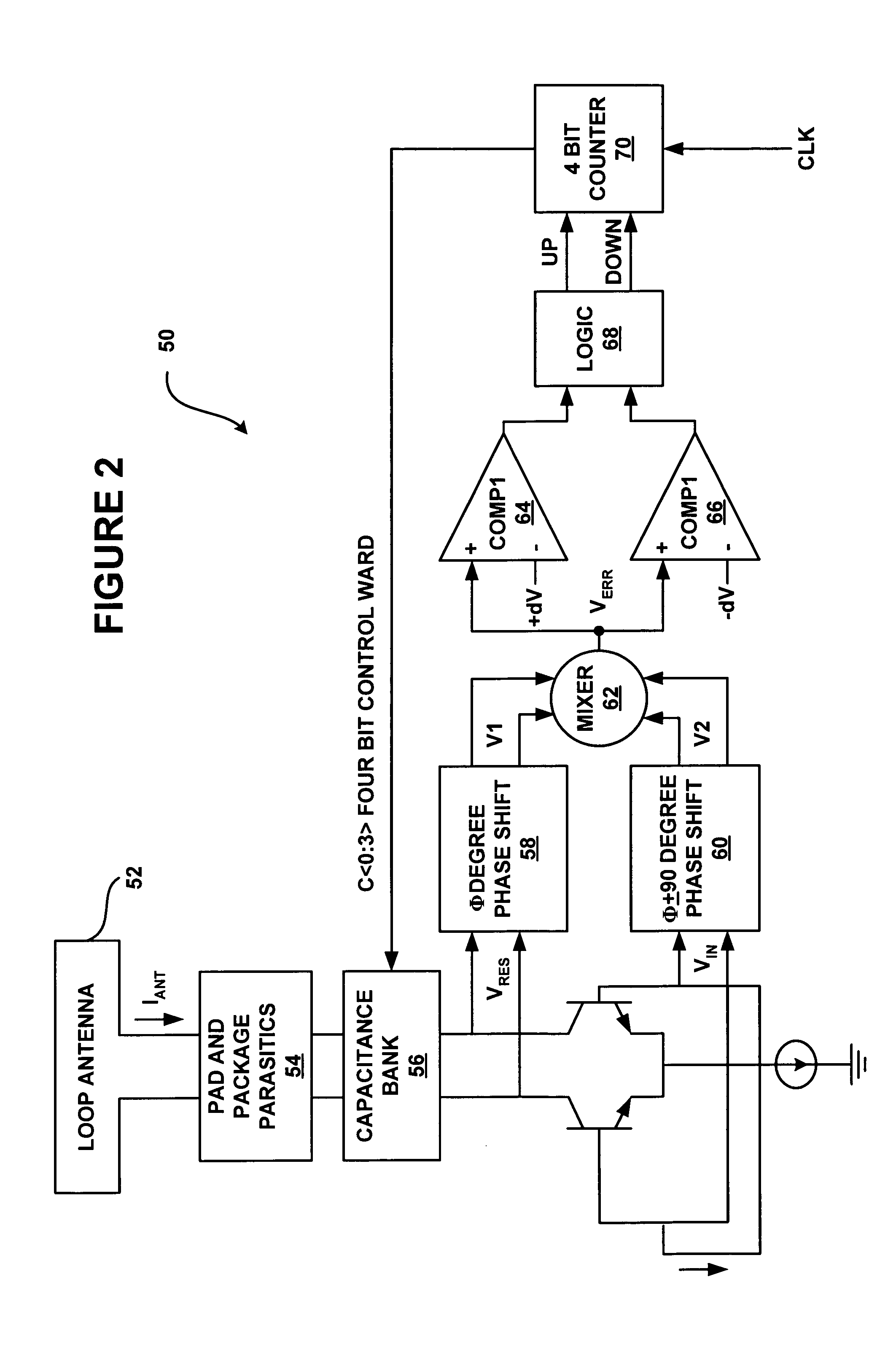
[0020] The present invention is directed toward a method and apparatus for tuning small resonant loop antennas in transceiver circuits.

[0021] To minimize the current consumption, external component count and size of an RF transmitter it is desirable to directly drive an integrated loop antenna having high input impedance. Small loop antennas need tuning capacitance to obtain antenna resonance at a desired operating frequency in order to improve radiation efficiency. The desired resonant frequency for a circuit may be affected by variations in integrated circuit processes, circuit packaging, and PCB manufacturing tolerances.

[0022] The antenna tuning circuit and method of the present invention identifies a de-tuned condition and acts in order to minimize the detuning. The present invention works on the principle that, when in resonance, the resonant voltage (Vres) and antenna current (Iant) on the complete resonator (antenna, package, plus tuning capacitance) are in phase. If a phas...


PUM


Abstract

Disclosed is a circuit and method for automatic tuning of a resonant circuit in a transceiver having a receiver and a transmitter that includes a power amplifier for driving the resonant circuit. During a transmit mode of the transceiver, a resonance voltage of the resonant circuit is compared to an input voltage signal to the power amplifier to determine an error signal that is converted into a control word. The control word drives an adjustable capacitance bank that is part of the resonant circuit. During a receive mode of the transceiver, the control word value is held constant to substantially maintain resonance of the resonant circuit during operation of the receiver.

Description

CROSS REFERENCE TO RELATED APPLICATIONS [0001] This patent application is a continuation-in-part of co-pending, commonly assigned, U.S. patent application Ser. No. 10 / 286,647, filed Nov. 1, 2002.FIELD OF THE INVENTION [0002] The present invention relates to transceiver circuits. More specifically, it relates to automatic tuning of an integrated loop antenna system of a transceiver circuit. BACKGROUND OF THE INVENTION [0003] A generally license free frequency band called the industrial-scientific-medical (ISM) band has emerged for short range low power applications, such as industrial controls, telemetry and low power data transmission. A range of frequencies from 300 MHz to 1 Ghz is generally provided for ISM. For example, the European ISM standard provides for operation at 433 MHz and at frequencies ranging from 800 MHz to 930 MHz. The US ISM standard provides for a band at 300 MHz and in a range from 902 MHz to 928 MHz. An ISM transceiver may, therefore, need to operate at more th...

Claims


Application Information

Patent Timeline
Patent Type & Authority Applications(United States)
IPC IPC(8): H01Q7/00H01Q23/00H04B1/04
CPCH01Q7/005H04B1/0458H01Q23/00
Inventor DE RUIJTER, HENDRICUSTOTH, GABORONODY, PETERHEGYI, ANDRASZOLOMY, ATTILAPARDOEN, MATTHIJS D.ERDELYI, JANOSMERNYEI, FERENC
Owner SILICON LAB INC
Why Eureka
Try Eureka