Cryogenic liquid natural gas recovery process

a cryogenic liquid and natural gas technology, applied in the field of cryogenic liquid natural gas recovery process, to achieve the effect of reducing the overall energy and fuel requirements, avoiding the need for dehydration, and reducing the capital investmen

Inactive Publication Date: 2005-01-13
HOWE BAKER ENGINEERS LTD
View PDF12 Cites 26 Cited by
  • Summary
  • Abstract
  • Description
  • Claims
  • Application Information

AI Technical Summary

Benefits of technology

[0005] As stated, our invention is directed to an improved process for the recovery of NGL from LNG, which avoids the need for dehydration, the removal of acid gases and other impurities. A further advantage of our process is that it significantly reduces the overall energy and fuel requirements because the residue gas compression req...

Problems solved by technology

Although there are many known processes, there is always a compromise ...

Method used


Image

  • Cryogenic liquid natural gas recovery process
  • Cryogenic liquid natural gas recovery process
  • Cryogenic liquid natural gas recovery process

Examples


Embodiment Construction

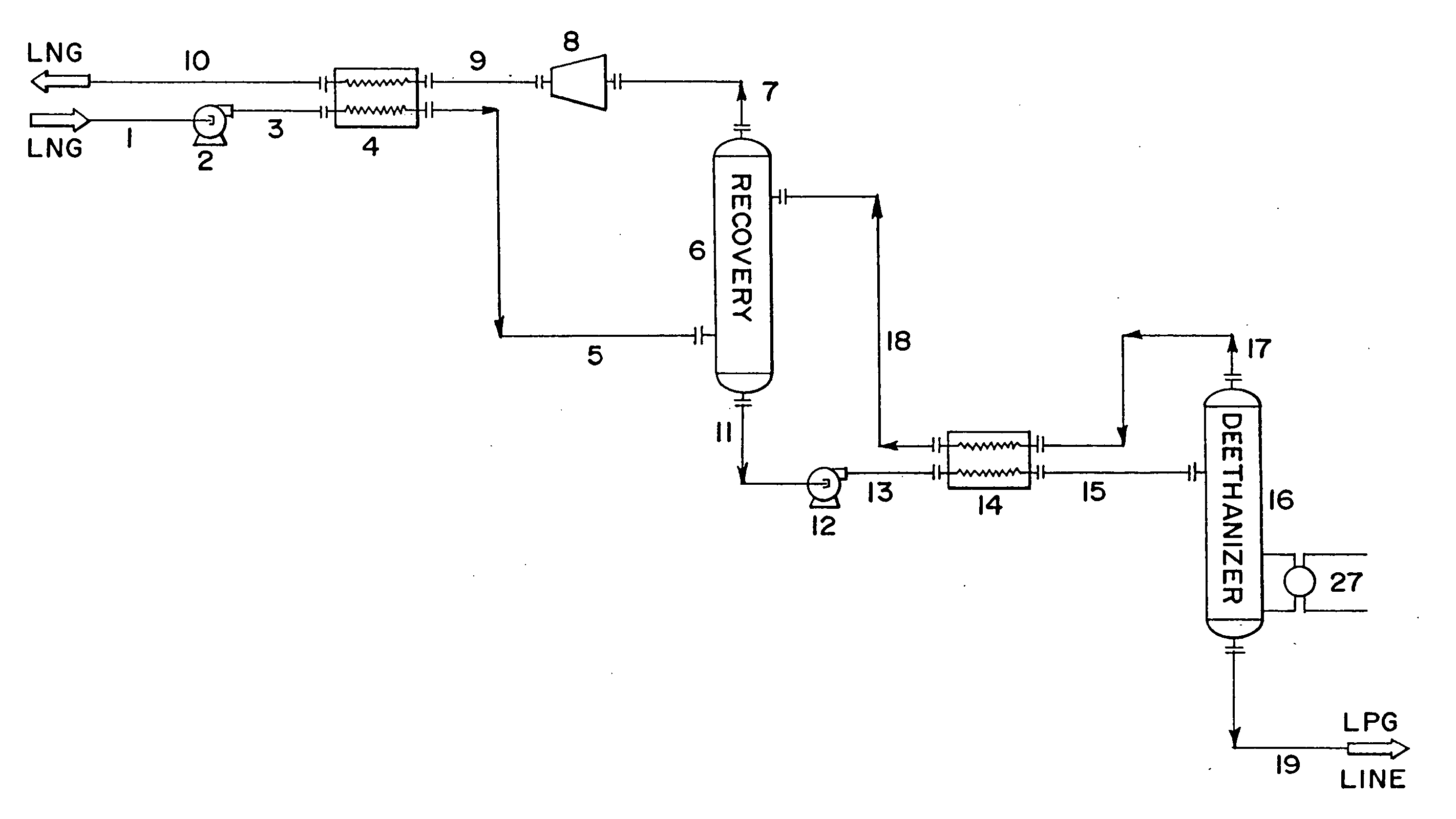
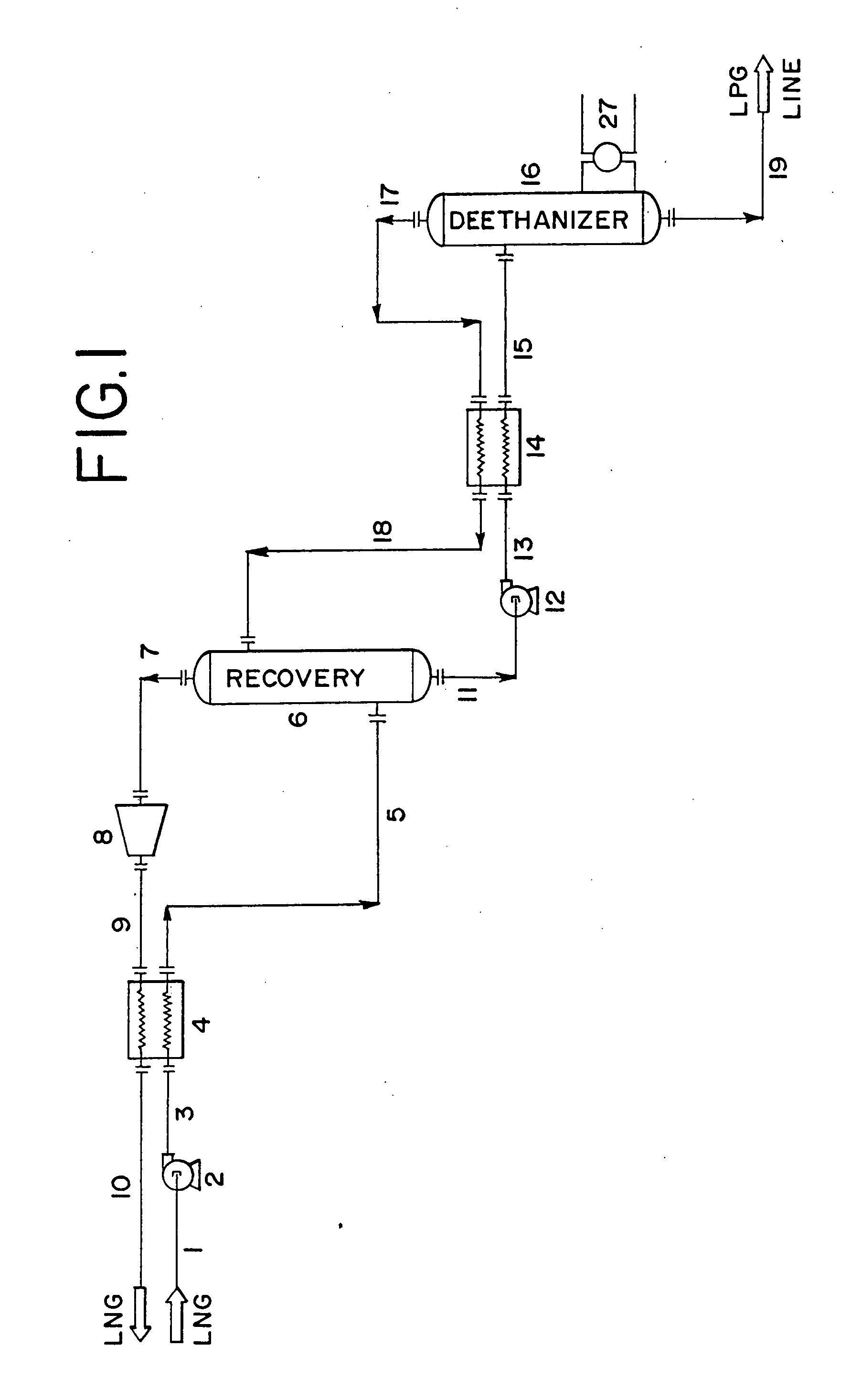
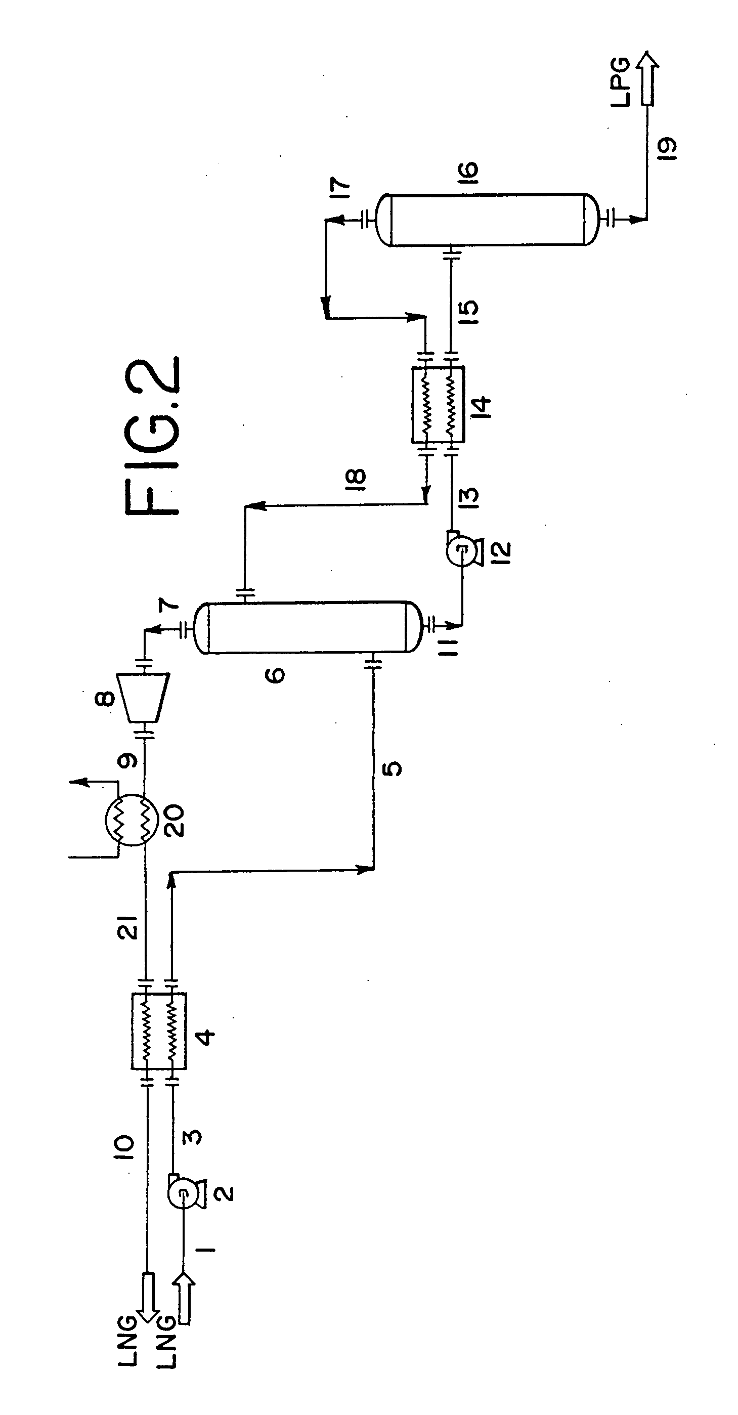
[0015] Natural gas liquids (NGL) are recovered from low-pressure liquefied natural gas (LNG) without the need for external refrigeration or feed turboexpanders as used in prior processes. Referring to FIG. 1, process 100 shows the incoming LNG feed stream 1 enters pump 2 at very low pressures, typically in the range of 0-5 psig and at a temperature of less than −200° F. Pump 2 may be any pump design typically used for pumping LNG provided that it is capable of increasing the pressure of the LNG several hundred pounds to approximately 100-500 psig, preferably the process range of 300-350 psig. The resultant stream 3 from pump 2 is warmed and partially vaporized by cross-exchange in heat exchanger 4 with substantially NGL-free residue gas in stream 9 exiting the process 100. After being warmed and partially vaporized, the resultant stream 5 from heat exchanger 4 is fed to recovery tower 6. Recovery tower 6 may be comprised of a single separation process or a series flow arrangement of...


PUM


Abstract

A process for the recovery of natural gas liquids (NGL) (ethane, ethylene, propane, propylene and heavier hydrocarbons) from liquefied natural gas (LNG) is disclosed. The LNG feed stream is split with at least one portion used as an external reflux, without prior treatment, to improve the separation and recovery of the natural gas liquids (NGL).

Description

FIELD OF THE INVENTION [0001] The present invention is directed toward the recovery of hydrocarbons heavier than methane from liquefied natural gas (LNG) and in particular to an improved process that provides for high-yield recovery of hydrocarbons heavier than methane while also producing a low BTU liquefied natural gas stream using minimal external heat supply. BACKGROUND OF THE INVENTION [0002] Natural gas typically contains up to 15 vol. % of hydrocarbons heavier than methane. Thus, natural gas is typically separated to provide a pipeline quality gaseous fraction and a less volatile liquid hydrocarbon fraction. These valuable natural gas liquids (NGL) are comprised of ethane, propane, butane, and minor amounts of other heavy hydrocarbons. In some circumstances, as an alternative to transportation in pipelines, natural gas at remote locations is liquefied and transported in special LNG tankers to appropriate LNG handling and storage terminals. The LNG can then be revaporized and ...

Claims


Application Information

Patent Timeline
IPC IPC(8): F25J3/02
CPCF25J3/0214F25J3/0233F25J3/0238F25J3/0242F25J2200/04F25J2245/90F25J2230/08F25J2230/60F25J2235/60F25J2245/02F25J2210/06F25J2200/78F25J2200/70F25J2200/40F25J3/02F25J3/0209
Inventor SCHROEDER, SCOTTREDDICK, KENNETH
Owner HOWE BAKER ENGINEERS LTD
Why Eureka
Try Eureka