Cascode circuit and integrated circuit having it

a cascode circuit and integrated circuit technology, applied in the field of cascode circuits, can solve the problems of low output power low efficiency of the cascode circuit, etc., and achieve high output power, high efficiency, and high power.

Active Publication Date: 2005-01-13
MITSUBISHI ELECTRIC CORP
View PDF5 Cites 57 Cited by
  • Summary
  • Abstract
  • Description
  • Claims
  • Application Information

AI Technical Summary

Benefits of technology

It is an object of the present invention to provide a cascode circuit which outputs high power and operates with high efficiency, and an integrated circuit having the cascode circuit.
The cascode circuit of the present invention includes a first field effect transistor which has a source terminal grounded, a second field effect transistor which has a source terminal connected to a drain terminal of the first field effect transistor, and a first capacitor connected between the source term

Problems solved by technology

Therefore, there is a problem that a voltage between the drain and source terminals of the first FET is maintained constant, so that the cascode circuit can not output a voltage proportional to the operation voltage thereof.
Further, in such a cascode circuit, there is also a problem that only the voltage between the drain and source terminals of the second FET is vari

Method used


Image

  • Cascode circuit and integrated circuit having it
  • Cascode circuit and integrated circuit having it
  • Cascode circuit and integrated circuit having it

Examples


1st embodiment

(1st Embodiment)

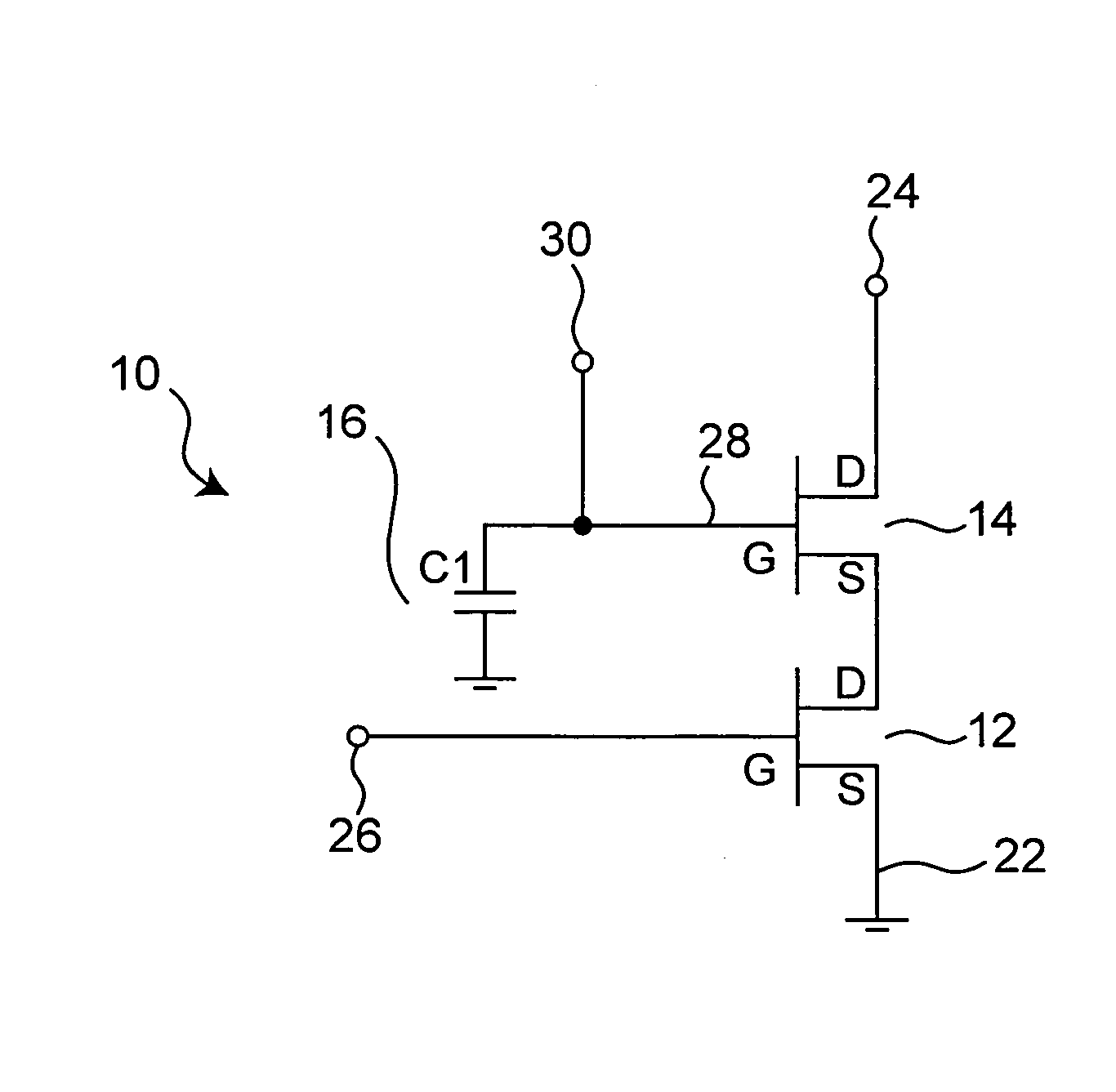
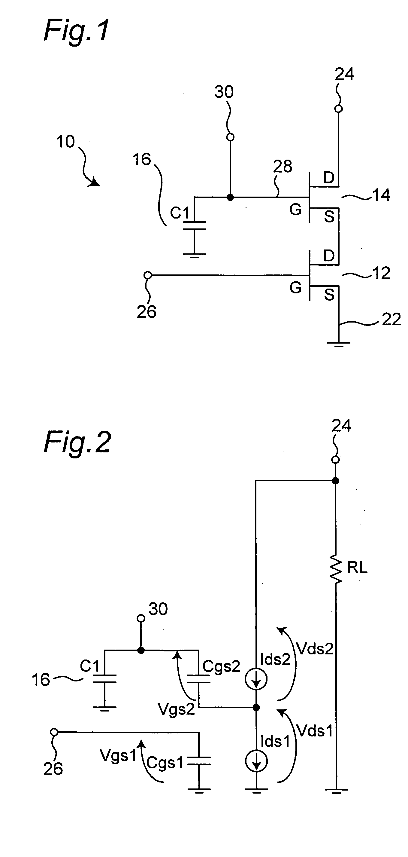
FIG. 1 shows a cascode circuit according to a first embodiment of the present invention. As shown in FIG. 1, the cascode circuit 10 includes two junction FETs which are cascode-connected successively. The cascode circuit 10 includes a first N-type junction FET 12, a second N-type junction FET 14, and a capacitor 16. Hereinafter, the junction FET is simply referred to as “FET”. The first FET 12 and the second FET 14 have the same characteristics. A source terminal (S) 22 of the first FET 12 is grounded, and a drain terminal (D) thereof is connected to a source terminal (S) of the second FET 14. A drain terminal (D) 24 of the second FET 14 is connected to an alternating current power supply (an average of the power supply voltage: Vdd). A gate terminal (G) 26 of the first FET 12, the source terminal (S) 22 of the first FET 12, and the drain terminal (D) 24 of the second FET 14 act as a gate terminal, a source terminal, and a drain terminal of the cascode circuit 10, re...

2nd embodiment

(2nd Embodiment)

FIG. 4 shows a cascode circuit according to a second embodiment of this invention. A cascode circuit 40 shown in FIG. 4 is different from the cascode circuit 10 shown in FIG. 1 in that the gate voltage setting terminal 30 is eliminated, and a first resistor 42 and a second resistor 44 are added. One end of the first resistor 42 is connected to the gate terminal 28 of the second FET 14, and the other end thereof is connected to the source terminal of the first FET 12 (that is, the other end thereof is “grounded”). The second resistor 44 is connected between the gate terminal 28 and the drain terminal 24 of the second FET 14.

In the cascode circuit 40 shown in FIG. 4, a voltage to be applied to the gate terminal 28 is determined by using the first resistor 42 and the second resistor 44, which divide a voltage between the drain terminal 24 of the second FET 14 and the ground. Thus, unlike the case in which the voltage is applied to the gate terminal 28 by using a gate ...

3rd embodiment

(3rd Embodiment)

FIG. 14 is a circuit diagram of a cascode circuit according to a third embodiment of this invention. The cascode circuit of the third embodiment is different from that of the second embodiment in that the one end of the first resistor 42 is not grounded but is connected to the gate terminal 26 of the first FET 12.

FIG. 15 is a top view of the integrated circuit having the cascode circuit of this embodiment. FIG. 15 shows an electrode pattern in which three cascode circuits are connected in parallel on the substrate 50. The electrode pattern shown in FIG. 15 is different from that shown in FIG. 6 in that an electrode 82 connected to the first gate electrode 68 is disposed adjacent to the electrode 72, instead of the electrode 76, that the first wire resistor 78, corresponding to the first resistor 42, is connected between the electrode 72 and the electrode 82, and that the second wire resistor 80, corresponding to the second resistor 44, is connected between the elect...


PUM


Abstract

A cascode circuit includes a first field effect transistor which has a source terminal grounded, a second field effect transistor which has a source terminal connected to a drain terminal of the first field effect transistor, and a first capacitor connected between the source terminal of the first field effect transistor and a gate terminal of the second field effect transistor. The first field effect transistor and the second field effect transistor are cascode-connected successively. A capacitance value of the first capacitor is 0.01 to 10 times that between the gate and source terminals of the second field effect transistor.

Description

BACKGROUND OF THE INVENTION 1. Field of the Invention The present invention relates to a cascode circuit used in a high frequency circuit, and an integrated circuit having the cascode circuit. 2. Description of the Related Art Cascode circuit, which includes field-effect transistors (hereinafter, referred to as “FETs”) cascode-connected successively (hereinafter, referred to as “cascode FET”), is used in a high frequency amplifier circuit of such as a cellular phone. The cascode circuit includes a first FET, a second FET and a capacitor. A source terminal of the first FET is grounded, a drain terminal of the first FET is connected to a source terminal of the second FET. A gate terminal of the first FET, the source terminal of the first FET, and a drain terminal of the second FET function as a gate terminal, a source terminal, and a drain terminal of the cascode circuit, respectively. A gate terminal of the second FET is grounded through a capacitor. As to this, refer to “Cascode...

Claims


Application Information

Patent Timeline
IPC IPC(8): H01L27/06H01L21/8232H01L27/095H01L29/80H03F1/22H03F3/189
CPCH03F3/189H03F1/223
Inventor INOUE, AKIRAGOTO, SEIKI
Owner MITSUBISHI ELECTRIC CORP
Why Eureka
Try Eureka