
Fusible alloy and thermal fuse

a fuse element and alloy technology, applied in the direction of thermally actuated switches, electric switches, electric devices, etc., can solve the problems of excessive heat generation of batteries, damage to electrical devices and batteries of mobile phones, breakdowns or improper operation, etc., to enhance the separation of the fuse elemen

Inactive Publication Date: 2005-01-13
PANASONIC CORP
View PDF17 Cites 16 Cited by
  • Summary
  • Abstract
  • Description
  • Claims
  • Application Information

AI Technical Summary

Benefits of technology

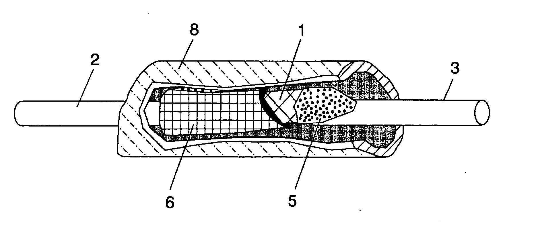
[0016] A thermal fuse of the present invention has a transparent or translucent cover and colored flux disposed inside the cover, so that the proper separation of the melted fuse element is enhanced.

Problems solved by technology

Electronic devices and batteries for mobile phones could suffer damage from overheating and the like.
For example, when a battery has a short circuit between the positive and the negative terminals by some reason, an abrupt discharge occurs, by which the battery generates excessive heat.
Because of the heat generation, the battery itself or electronic components disposed close to the battery could cause breakdowns or operate improperly.
When abnormal overheat occurs in the circuit, the fuse element melts by the raised temperature, whereby electrical connections are broken down.
With such structures, a problem occurs in sealing the opening of the case—too much process time required for sealing degrades durability, so that the elements have exhibited a wide range of variations in quality.
In particular, since the end walls of the case adjacent to the openings rise straight up, the sealing process requires extra steps, for example, injecting the sealer into the inside of the case and covering the openings with a large amount of the sealer, thereby consuming the manufacturing time.
Besides, spillover of the sealer to outside the case has frequently occurred.
If the sealer having a high coefficient of thermal expansion spills out the case and adheres to the case and electric terminals, an undesired stress is applied to the terminal when the temperature rises, whereby the intended behavior of the fuse at the operating temperature is interrupted.
The fusible alloy itself may melt at a high temperature even in such unintended state, however, the thermal fuse may be unable to work in the target temperature-range of 130-190° C.

Method used


Image

  • Fusible alloy and thermal fuse
  • Fusible alloy and thermal fuse
  • Fusible alloy and thermal fuse

Examples


first exemplary embodiment

[0062] First Exemplary Embodiment

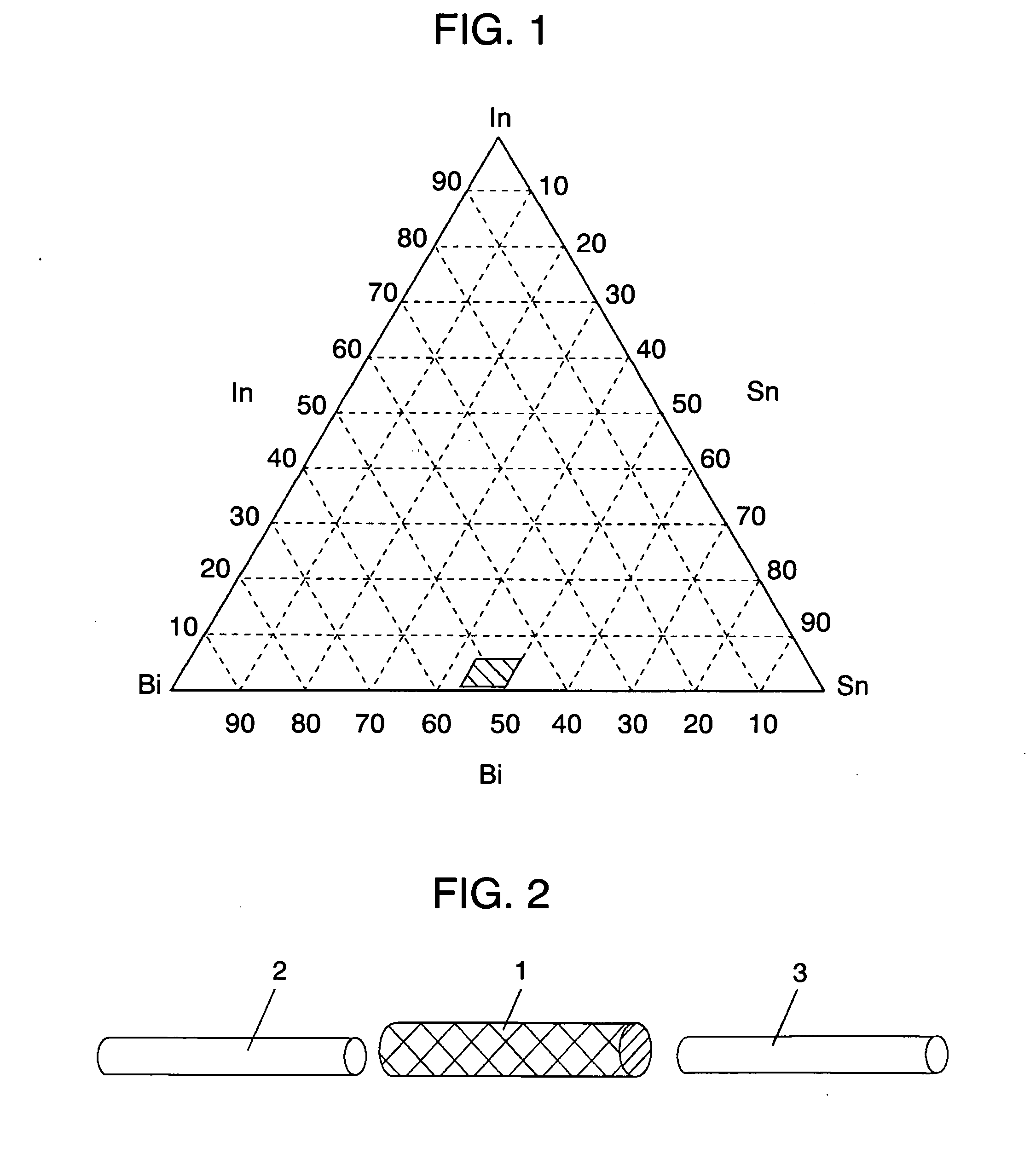
[0063] First will be described the relationship between a fusing temperature and liquidus / solidus temperatures of fusible alloy. When fusible alloy melts by heating, the alloy generally experiences changes in the order of the solid phase, the solid-liquid coexisting phase and then the liquid phase. In the process, the boundary temperature between the solid phase and the solid-liquid coexisting phase is described as a solidus temperature; similarly, the boundary between the solid-liquid coexisting phase and the liquid phase is described as a liquidus temperature. A fusible alloy has a fusing temperature at somewhere (fairly closer to the liquidus temperature) between the solidus temperature and the liquidus temperature. The larger the difference between a solidus temperature and a liquidus temperature in a fusible alloy is, more increase variations in fusing temperatures are. On the other hand, the smaller the difference between the two temperatures a...

experiment 1

[0076] (Experiment 1)

[0077] According to composition ratio predetermined by each sample, a first fusible alloy was prepared and then employed for the fuse element of a thermal fuse of each sample.

[0078] In preparing the samples, In of at least 99.99% purity, Sn of at least 99.99% purity, and Bi of at least 99.99% purity were weighed according to the percentage by weight determined by each sample and then melted in a fusing furnace. The metals were kept in the furnace until each metal completely melted. In an advanced state of fusing, the mixture was well stirred to obtain an alloy having uniform distribution in composition. After being stirred well and completely fused, the mixture was slowly cooled at room temperature. Through the process above, each sample was obtained. For each fusible alloy, the liquidus and the solidus temperatures and the difference between the two temperatures were measured and evaluated whether or not each sample provides a desired fusing temperature and fu...

second exemplary embodiment

[0085] Second Exemplary Embodiment

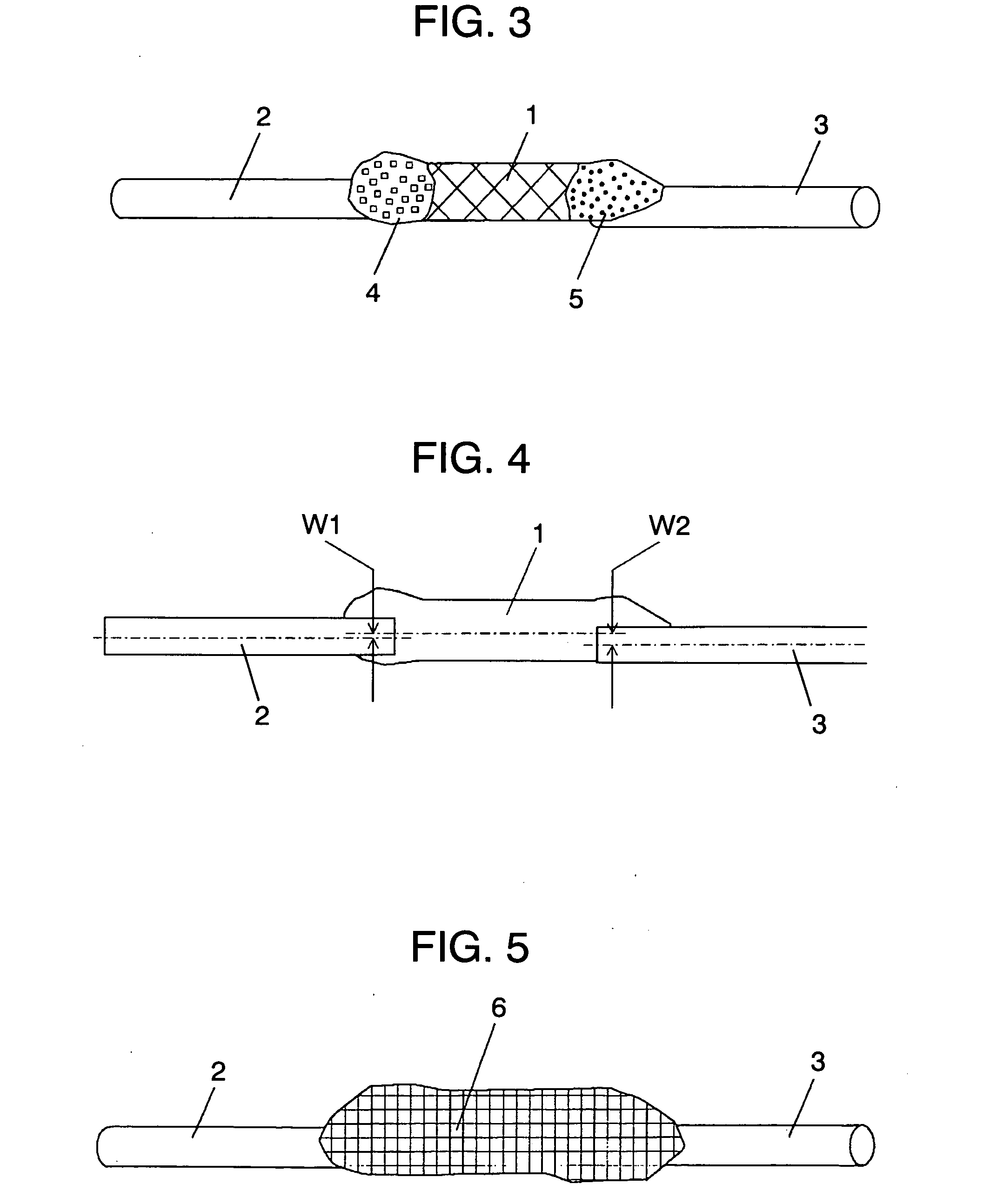
[0086]FIGS. 2 through 5 illustrate the fuse section of the second embodiment of the present invention.

[0087] Fuse element 1 is formed of the first fusible alloy described in the first embodiment. Although FIG. 2 shows substantially linear fuse element 1, it is not limited thereto; the fuse element can be formed into various shapes, for example, a plate or oval shape. Fuse element 1 is the section that actually fuses in a thermal fuse (will be described later), and the essential part of determining the operating temperature of the thermal fuse.

[0088] Here will be described an example of manufacturing fuse element 1. After fusing an alloy having a predetermined composition ratio of elements, inject the melted alloy into a casting cylinder, and then cool it to obtain a solid state. With the application of high pressure, extrude the solidified cylindrical alloy, through an extruder or the like, to form into a wire. Then, the alloy wire is cut to a pre...


PUM


Abstract

The thermal fuse of the present invention contains a fuse element 1 that is formed of a fusible alloy having a composition of 43.5-50 wt % Sn, 0.1-5 wt % In, and balance being Bi and inevitable impurities, or a fusible alloy having a composition of 5-33 wt % In, 4.7-15.5 wt % Zn, and balance being Sn and inevitable impurities; a pair of electric terminals 2, 3 connected to the fuse element; and case 8 for accommodating at least the fuse element 1. The opening end of case 8 has a predetermined shape. By employing the structure above, a thermal fuse having an operating temperature as high as 130-190° C. can be easily obtained.

Description

TECHNICAL FIELD [0001] The present invention relates to a fusible alloy for a fuse, and a thermal fuse formed of the fusible alloy preferably employed for protecting electronic devices from damage caused by abnormal overheat, over current, and the like. BACKGROUND OF THE INVENTION [0002] Electronic devices and batteries for mobile phones could suffer damage from overheating and the like. To take precautions against such possible damage due to abnormal overheat and other causes, a thermal fuse should preferably be fixed to them. For example, when a battery has a short circuit between the positive and the negative terminals by some reason, an abrupt discharge occurs, by which the battery generates excessive heat. Because of the heat generation, the battery itself or electronic components disposed close to the battery could cause breakdowns or operate improperly. In a battery charger and an adaptor, generated heat can increase the temperature of the device; a thermal fuse should prefer...

Claims


Application Information

Patent Timeline
IPC IPC(8): H01H37/76
CPCH01H2037/768H01H37/761
Inventor WADA, TATSUYAOTSUKA, SHINICHIMUKAI, TAKAHIROIZAKI, MASATOSHI
Owner PANASONIC CORP
Learn More