System and method for impedance matching an antenna to sub-bands in a communication band

Inactive Publication Date: 2005-01-13
KYOCERA CORP
View PDF98 Cites 173 Cited by
  • Summary
  • Abstract
  • Description
  • Claims
  • Application Information

AI Technical Summary

Benefits of technology

[0020] The present invention describes an antenna matching system that can be tuned to provide an optimal matching impedance at selected channels, or sub-bands in a communication band. The optimal matching permits greater efficiency, a lower receiver noise floor, lower transmitter power, or optimal bandwidth, without the compl

Problems solved by technology

While the antenna may resonant fairly well across an entire communication band, it cannot be optimally tuned for every channel in the communication band.
Thus, the wide-band tuning comes at the expense of optimal efficiency.
However, it is difficult to locate discrete antennas in a portable wireless device when the device incorporates a number of transceivers, each operating in a different communication band, or one transceiver that can be tuned to operate in a number of communications bands.
Such a design may be inadequate to cover all the required frequencies (communication bands), however.
However, the widening of the higher band, to improve GPS and PCS performance, comes at the expense of cellular band performance.
Conventional measurement techniques, however, have characterized fe

Method used


Image

  • System and method for impedance matching an antenna to sub-bands in a communication band
  • System and method for impedance matching an antenna to sub-bands in a communication band
  • System and method for impedance matching an antenna to sub-bands in a communication band

Examples


Embodiment Construction

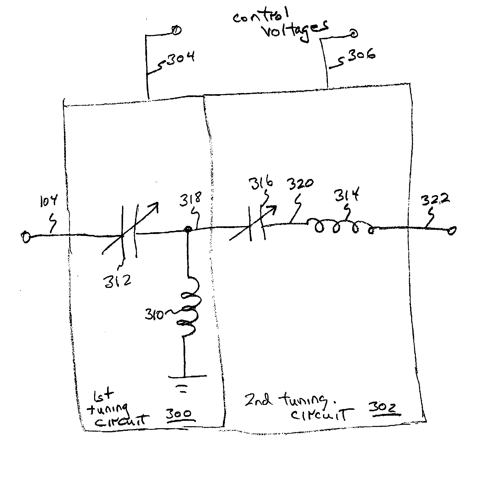
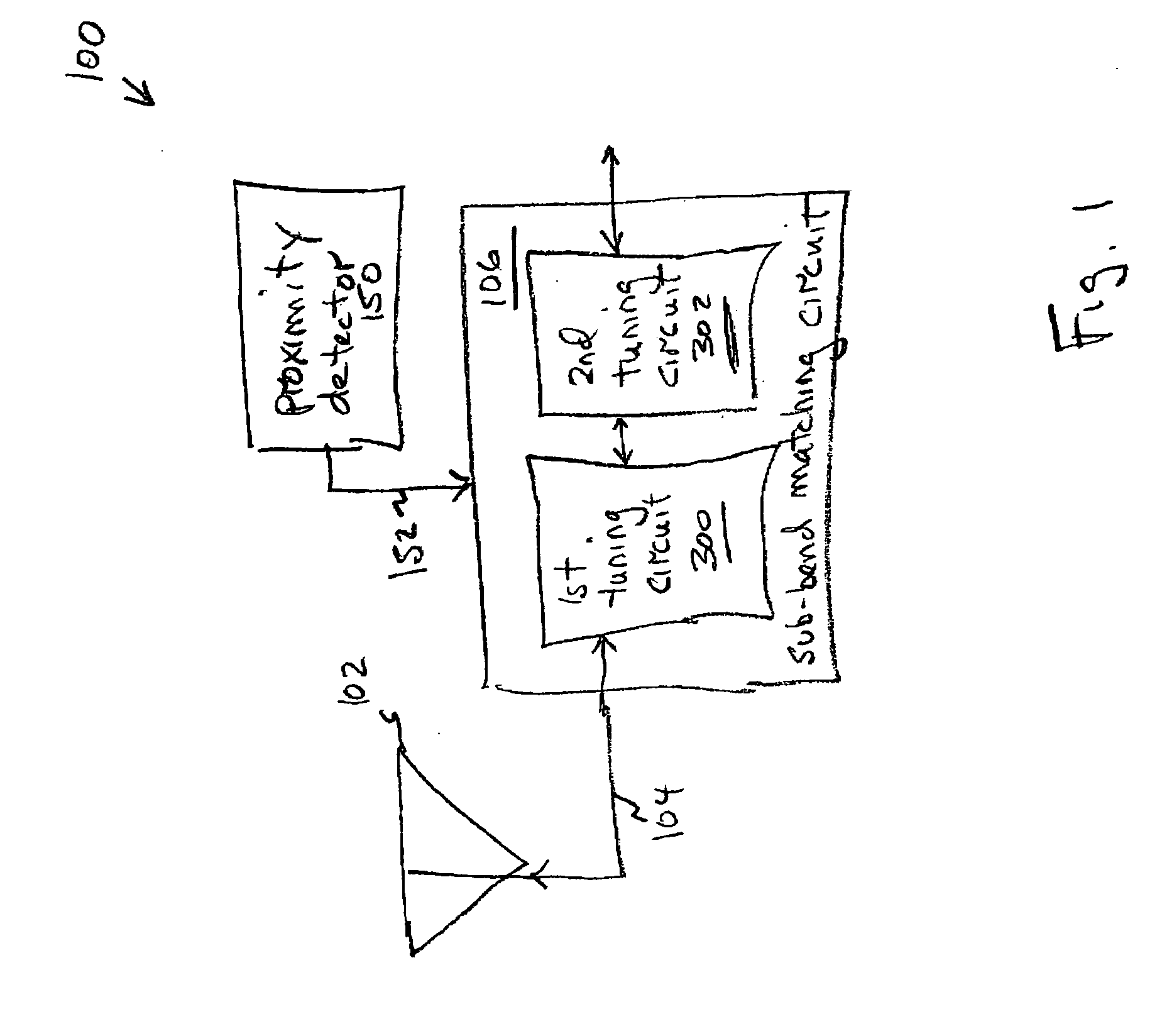
[0043]FIG. 1 is a schematic block diagram of the present invention antenna matching system for selectively matching a communication bandwidth segment impedance. The system 100 comprises an antenna 102 having an interface port on line 104 with a frequency-dependent impedance. A sub-band matching circuit 106 has an output port on line 104 connected to the antenna interface port. The sub-band matching circuit 106 selectively supplies a conjugate impedance at a sub-band of a first communication band. In its simplest form, the sub-band matching circuit 106 selectively supplies the conjugate impedance at a low end of the first communication band and at a high end of the first communication band.

[0044] It should be understood that an antenna will function to some extent, even if poorly matched. Some conventional antenna / matching circuit designs are able to cover an entire communication band by providing a widely varying match across the entire band. A poorly matched antenna is likely to r...


PUM


Abstract

A sub-band antenna matching method and an antenna matching system for selectively matching a communication bandwidth segment impedance have been provided. The method comprises: accepting a frequency-dependent impedance from an antenna; and, selectively supplying a conjugate impedance match for the antenna at a sub-band of a first communication band. In some aspects, the method selectively supplies a conjugate impedance match for the antenna at a sub-band of a second communication band. More specifically, the method comprises: tuning a first tuning circuit to a first frequency; simultaneously tuning a second tuning circuit to a second frequency to match the antenna at a low end of the first communication band. Likewise, the first tuning circuit is tuned to a third frequency and the second tuning circuit is tuned to a fourth frequency to match the antenna at a high end of the first communication band in response to the third and fourth frequencies.

Description

RELATED APPLICATIONS [0001] This application is related to and is a continuation-in-part of U.S. applications “FERROELECTRIC ANTENNA AND METHOD FOR TUNING SAME”, Ser. No. 10 / 117,628, filed on Apr. 4, 2002; “INVERTED-F FERROELECTRIC ANTENNA”, Ser. No. 10 / 120,603, filed on Apr. 9, 2002; and “TUNABLE ANTENNA MATCHING CIRCUIT”, Ser. No. 10 / 075,896, filed on Feb. 12, 2002, all of which are incorporated herein by reference. [0002] This application is related to U.S. APPLICATIONS “TUNABLE HORN ANTENNA”, Ser. No. 10 / 122,399, filed on Apr. 12, 2002; “TUNABLE WAVEGUIDE ANTENNA”, Ser. No. 10 / 122,968, filed on Apr. 11, 2002; “TUNABLE DIPOLE ANTENNA”, Ser. No. 10 / 121,773, filed on Apr. 11, 2002; and “TUNABLE MATCHING CIRCUIT”, Ser. No. 09 / 927,136, filed on Aug. 10, 2001, all of which are incorporated herein by reference. [0003] This application is also related to the following two U.S. applications filed on the same day as the present application and having the same inventors, and which applicat...

Claims


Application Information

Patent Timeline
IPC IPC(8): H01P5/04H01Q1/00H01Q1/24H01Q9/04H01Q9/16H01Q9/30H01Q9/42H01Q13/02H01Q13/06H01Q13/20H01Q13/22
CPCG01R27/2694H03H7/38H01L27/0808H01P1/203H01P1/20336H01P1/20363H01P1/20381H01P1/2039H01P1/2056H01P1/213H01P5/04H01Q1/00H01Q1/243H01Q3/44H01Q9/0407H01Q9/0421H01Q9/0442H01Q9/16H01Q9/28H01Q9/30H01Q9/42H01Q13/02H01Q13/06H01Q13/203H01Q13/22H03B5/04H03B5/1841H03B5/362H03F1/56H03F3/191H03F2200/294H03F2200/372H03J5/246H03L1/022H03L7/18H04B1/0053H04B1/0458H04B1/30H01G7/06
Inventor FABREGA-SANCHEZ, JORGEPOILASNE, GREGORYTONCICH, STANLEY S.TRAN, ALLEN
Owner KYOCERA CORP
Why Eureka
Try Eureka