Process and apparatus for fabricating precise microstructures and polymeric molds for making same

a technology of polymeric molds and microstructures, applied in the field of process and equipment for fabricating precise microstructures and polymeric molds for making same, can solve the problem of only limited speed, and achieve the effect of multiple cost and process advantages, fast and less expensive, and without cost or tim

Inactive Publication Date: 2005-01-13
10X TECH
View PDF29 Cites 42 Cited by
  • Summary
  • Abstract
  • Description
  • Claims
  • Application Information

AI Technical Summary

Benefits of technology

[0028] An important advantage of the invention is the ability to make polymeric molds as part of the apparatus to form precision microstructures. Since many of these powdered polymers and particularly the UV cure version can be deposited and polymerized into a mold at low cure temperatures, a polymeric mold becomes a faster and less expensive alternative to metal molds described in prior art.
[0029] Such a polymer mold has multiple cost and process advantages. By fabricating a polymeric mold consisting of high glass transition polymer or thermosetting polymer, it is possible to replicate lower glass transition polymers using the process described in U.S. Pat. No. 4,486,363 or any improved versions of hot polymer embossing without the cost or time required to build large cylindrical metal molds.
[0030] Apparatus and methods are disclosed for fabricating a polymeric mold by electrostatically applying a powdered polymer layer on to a master microstructured pattern. Master patterns can be made by a number of recognized methods such as diamond turning, ruling, deep reactive ion etching (DRIE) or other techniques that provide such patterns. The master pattern or an electroformed copy of the master pattern can be used to make polymeric copies quickly and inexpensively that can be assembled by tiling methods known in various industries. This assembly of parts into a larger mold can be used in conjunction with further disclosed assembly apparatus such as die cutting and precision positioning equipment to provide larger molds for use in fabricating microstructured products.
[0031] It has also been demonstrated that pieces of a polymer film mold can be adhered to a stronger backing such as stainless steel or other suitable substrates that would give the composite additional strength and durability as well as electrostatic conductivity.
[0032] Another method to make a polymeric mold would be to provide a small and inexpensive electroformed mandrel to fabricate a polymer mold of any length or even continuous rolls of such molds by the use of a scaled down version of the apparatus described in U.S. Pat. Nos. 4,486,363 or 4,601,861.
[0033] Yet another method to make a polymeric mold would be to first fashion a small mold as a small continuous belt, then apply a polymer layer continuously that will provide replication of the small mold to provide a mold of any required length.

Problems solved by technology

Powder is applied to the mold from the bottom up eliminating the possibility of air being trapped and speed is only limited by the melt time and cure rate of the polymer.

Method used


Image

  • Process and apparatus for fabricating precise microstructures and polymeric molds for making same
  • Process and apparatus for fabricating precise microstructures and polymeric molds for making same
  • Process and apparatus for fabricating precise microstructures and polymeric molds for making same

Examples


Embodiment Construction

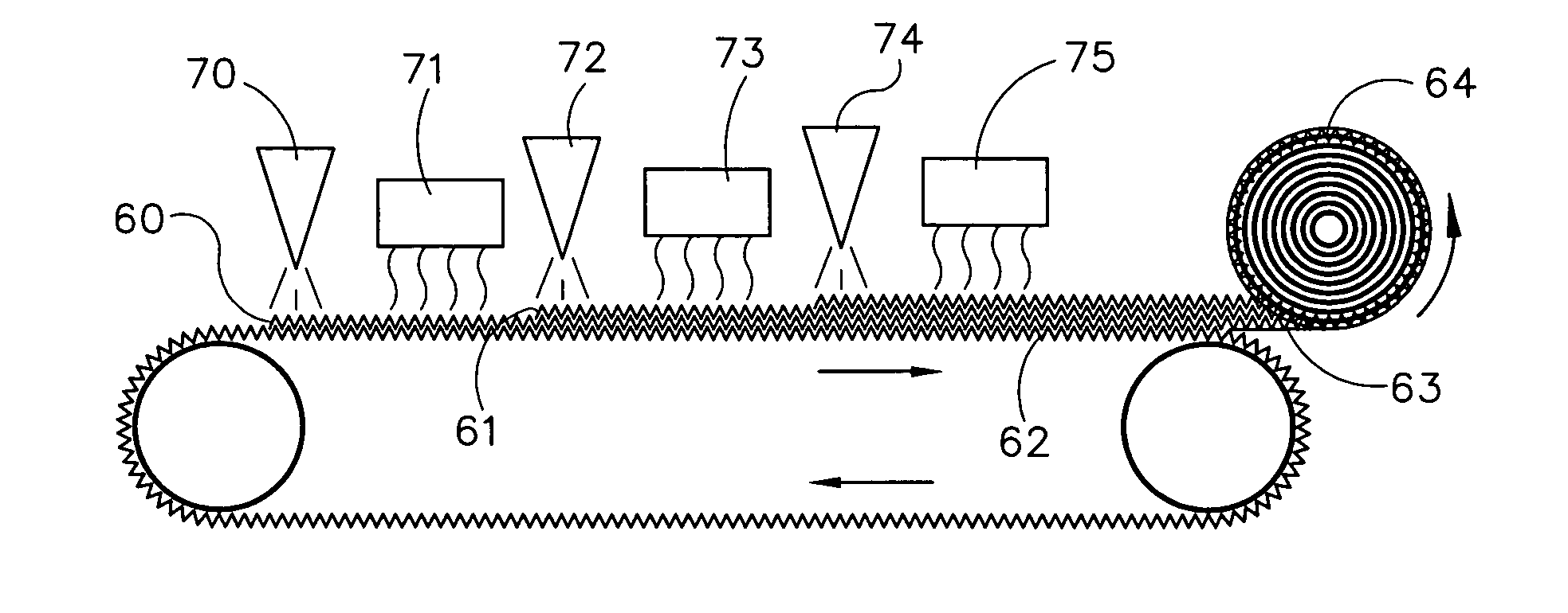
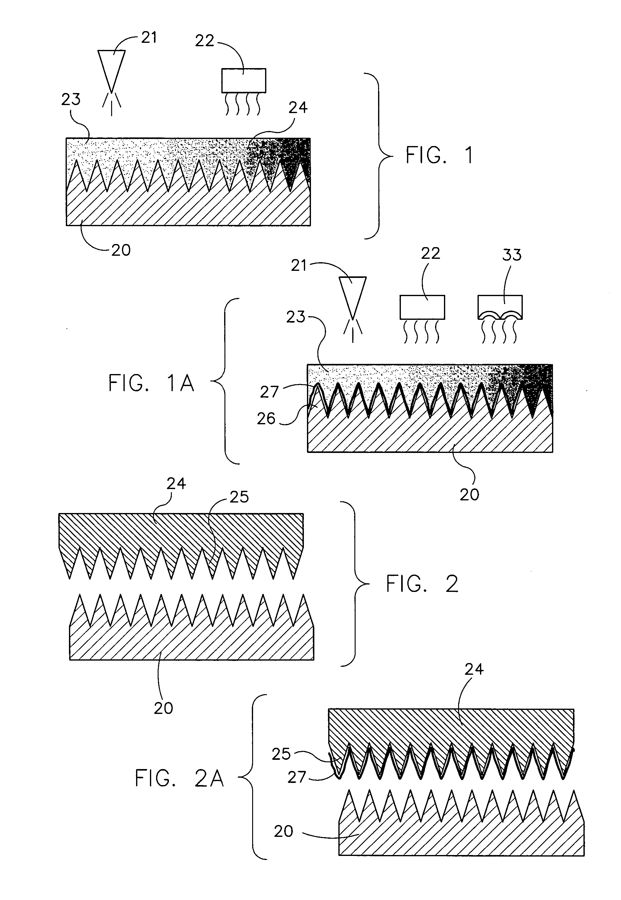
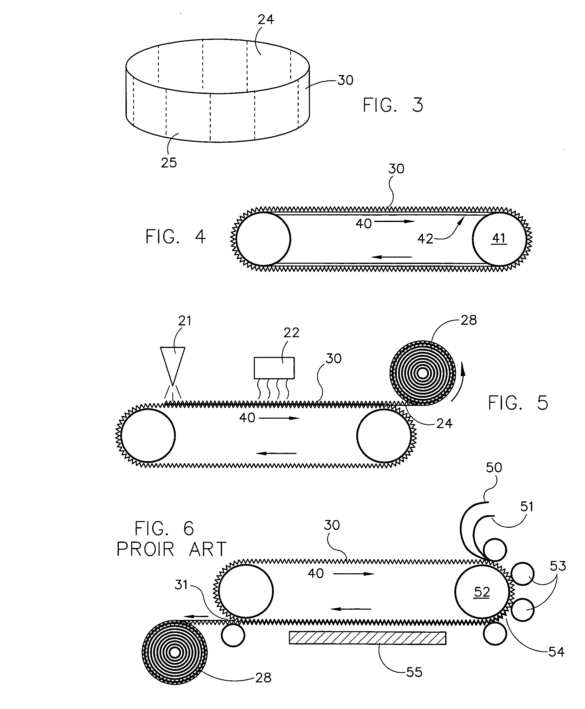
[0073] Referring to FIG. 1, a method to make polymeric mold sections is shown including a master pattern 20 made of electrodeposited nickel having a representative lenticular microstructure on the surface. Metal molds or tools for producing such devices are well known in the optics art.

[0074] An electrostatic gun 21 such as Wagner's Corona PEM-C3 Manual Spray Gun is used to apply a 0.004″ layer of epoxy based 445-100-1 CORVEL® GREEN powder 3 from Rohm and Haas Morton Powder Coatings, with a particle size of 10 microns. A source of infra red radiation 22 such as an electric or gas IR emitter at a temperature of 350° F. (176° C.) for two minutes is used to melt and flow the powder 23 which then cures as a polymer film 24. The master pattern 20 may be metal or polymeric as long as it is dimensionally stable at the cure temperature required for the polymers being applied. One of the primary advantages of using powder to form the polymeric layer over the master pattern is that it fills ...


PUM

PropertyMeasurementUnit
thicknessaaaaaaaaaa
thicknessaaaaaaaaaa
thicknessaaaaaaaaaa

Abstract

There is disclosed a method and apparatus for producing a polymeric film that accurately replicates a complex mold surface at least a portion of which surface has microstructured or nano-structured dimensions. A polymeric powder is electrodeposited on an underlying mold surface. Then the powder is cured to create a polymeric film. Finally the film is removed from the mold surface.

Description

[0001] This application claims the benefit of U.S. provisional patent application Ser. No. 60 / 485,268, entitled “A Process And Apparatus for Fabricating Precise Microstructures And Polymeric Molds for Making Same.”BACKGROUND OF THE INVENTION [0002] Fabrication of microstructured and nano-structured products known to be of interest in various industries include arrays of structured elements having optical applications, such as lenticular lenses, Fresnel lenses, light guides, diffusers, retro-reflective films, micro-lens arrays, brightness enhancement film (BEF) and LED arrays. Other applications include , biomedical components, micro-fluidic products, tissue culture media, micro-electrical-mechanical (MEMS), micro-acoustical, Chemical Mechanical Planerization (CMP), fuel cells, and other geometries that benefit from high speed, precision, microfabrication technology that provides high volume commercialization at economical cost. [0003] The present invention has novel advantages becau...

Claims


Application Information

Patent Timeline
Patent Type & Authority Applications(United States)
IPC IPC(8): B29C33/42B29C39/14B29C43/02B29C43/22B29C43/48B32B27/08B81C99/00C08J7/043
CPCB29C33/424B29C39/148B29C43/021B29C43/222B29C43/48B29L2011/0016Y10T428/24479B81C99/009C08J7/047Y10T428/24273Y10T428/24355Y10T428/24612B32B27/08C08J7/0427C08J7/043
Inventor PRICONE, ROBERT M.
Owner 10X TECH
Why Eureka
Try Eureka