Content distribution system and content distribution method

a content distribution system and content technology, applied in the field of content distribution system and content distribution method, can solve the problems of inability to cope with huge requests, limitation of the distribution bandwidth increase the workload of so as to reduce the load placed on the distribution server device, reduce the installation cost and the operational cost, and suppress the waiting period of clients

Inactive Publication Date: 2005-01-13
NEC CORP
View PDF15 Cites 15 Cited by
  • Summary
  • Abstract
  • Description
  • Claims
  • Application Information

AI Technical Summary

Benefits of technology

[0031] A first effect of the present invention is to reduce the load placed on the distribution server device. This is because the stream data is distributed to all client devices using the multicast tree consisting of the plural client devices even when requests from the plural client devices are concentrated on the distribution server.
[0032] A second effect of the present invention is to suppress waiting periods of clients for playback to be short. This is because the stream data converted using an algorithm of the near video on demand can take timings to start playing back in short cycles.
[0033] A third effect of the present invention is to reduce the installation cost and the operational costs of the content distribution system. This is because any specific installation for establishing multicast distribution network is not required since distribution is performed by establishing multicast tree among plural client devices requesting distribution. At the same time, the burden of managing the installation is reduced. Further, there is no need to deploy mirror servers or cache servers corresponding to the distribution scale, whereby the cost required for such an installation can be saved, and the burden of managing the installation is also reduced.
[0034] A forth effect of the present invention is that near video on demand can be easily introduced. This is because the multicast network is established on an upper layer than the IP layer, which enables near video on demand distribution to be realized on an IP network in which IP multicast is not supported.

Problems solved by technology

As the number of users increases, the cost and the distribution bandwidth become enormous.
Further, the distribution bandwidth of the distribution server device has a limitation, which causes a problem of not being able to cope with huge requests.
In other words, they do not offer any effect of reducing the distribution bandwidth as a whole.
Thus, if the distribution scale is enlarged, the installation cost or the operating cost increases proportionally.
In order to realize IP multicast distribution, a network including routers corresponding to the IP multicast is required, and also the installation cost for routers corresponding to the IP multicast is required.
Further, there is a disadvantage that it is quite difficult to introduce on the Internet where the IP multicast is not supported.
However, this method has a disadvantage as a distribution system using an end-system multicast tree.
Although this system is suitable for live distribution in which distribution starts at a predetermined time, it is not suitable for VOD distribution in which distribution starts at a time that a client requests.
Further, the mirroring method and the cache method require installation and management corresponding to the distribution scale, whereby the installation cost and operational cost increase.
On the other hand, in the NVOD distribution system, although it is expected to use IP multicast, it is difficult to be introduced on an IP network where the IP multicast is not supported.
In order to support the IP multicast, routers corresponding to the IP multicast must be deployed, which requires a high installation cost.
Moreover, the cost for managing and operating the routers increases.
Further, in the case of end-system multicast, the same content is distributed to all clients almost at the same time, which is difficult to start playing back with a short waiting time period or to start playing back responsive to a playback request from a client.
As described above, there has been no content distribution system conventionally which reduces the load placed on the distribution server device, which lowers installation and operational costs, which is easily introduced in a wide area, and which provides short waiting time periods for clients.

Method used


Image

  • Content distribution system and content distribution method
  • Content distribution system and content distribution method
  • Content distribution system and content distribution method

Examples


embodiment 1

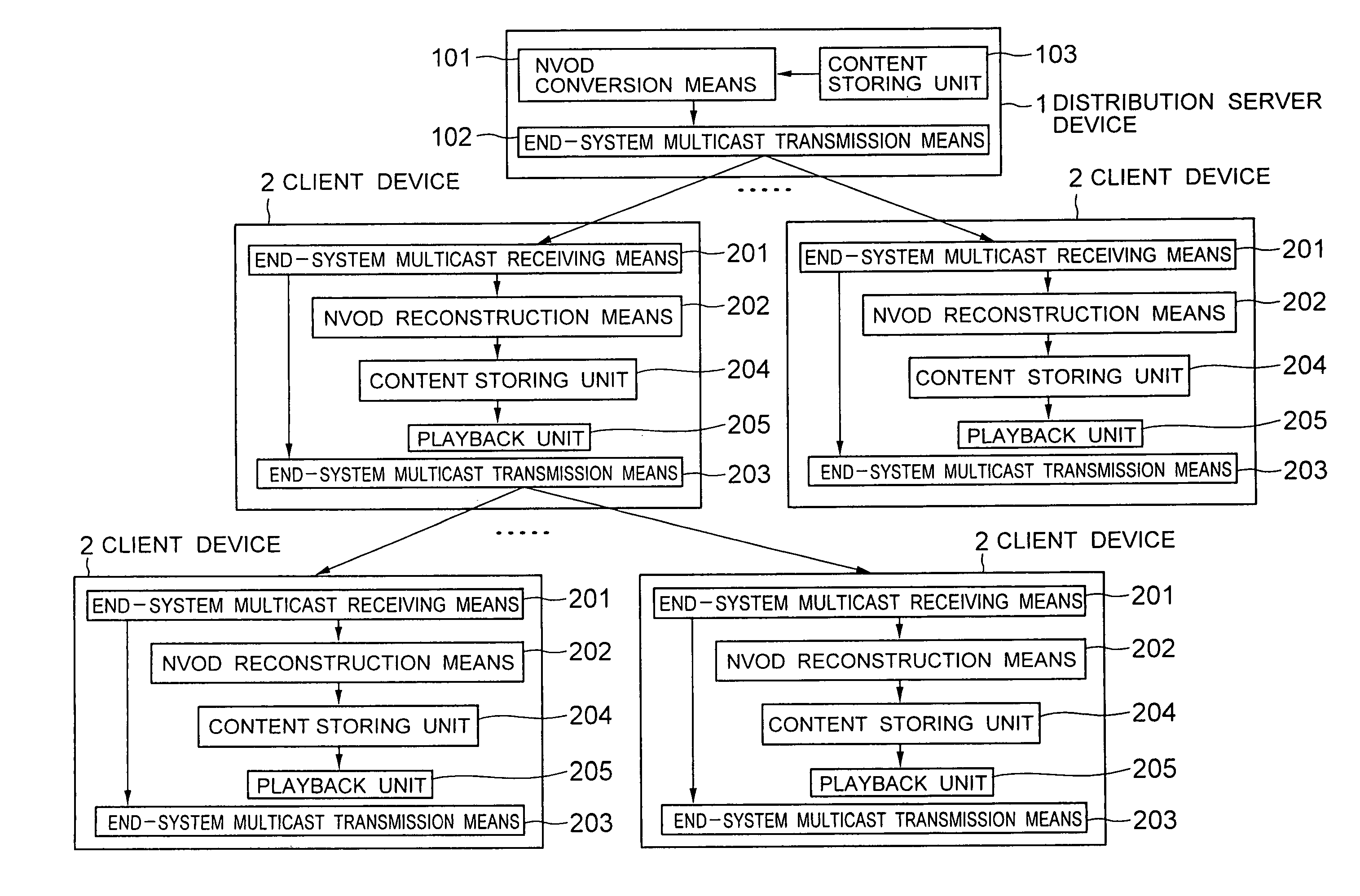
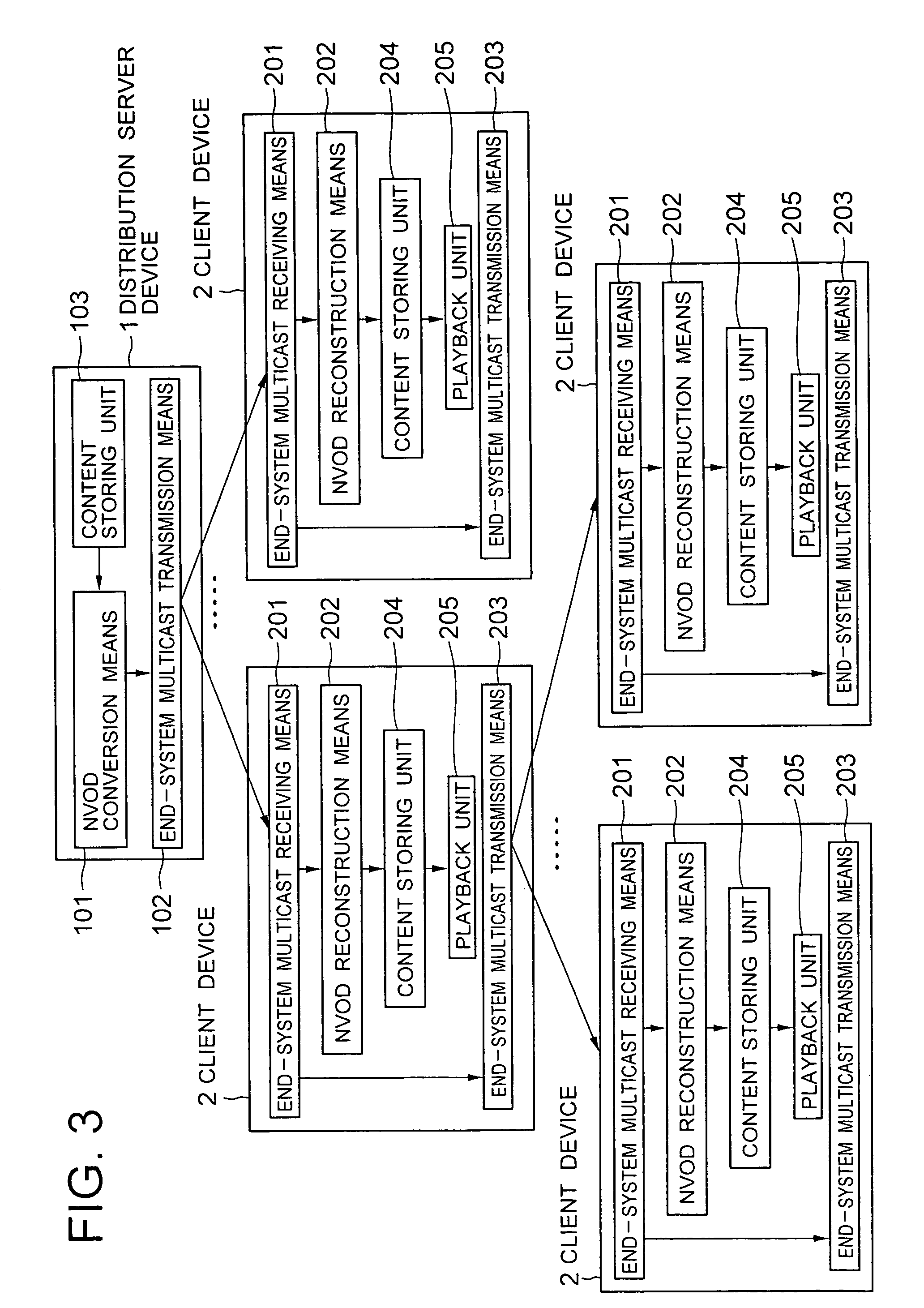
[0051] In FIG. 3, a content distribution system according to a first embodiment of the present invention comprises a distribution server device 1 such as a server computer and client devices 2 such as personal computers.

[0052] The distribution server device 1 includes a near-video-on-demand (NVOD) conversion means 101, an end-system multicast transmission means 102, and a content storing unit 103 which stores contents to be distributed.

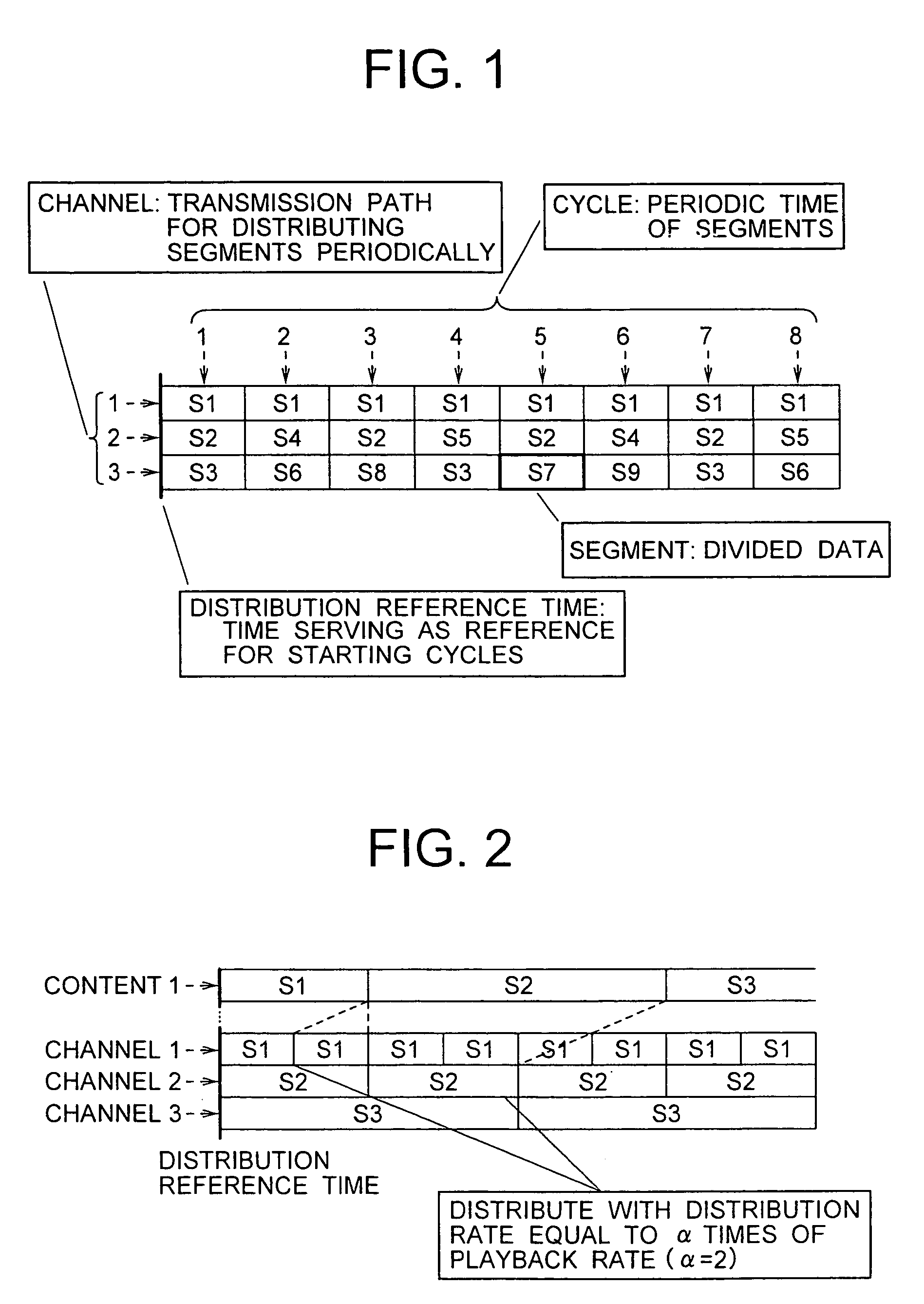
[0053] The NVOD conversion means 101 reads out a content from the content storing unit 103 and converts it into stream data in accordance with an algorithm of the NVOD.

[0054] The end-system multicast transmission means 102 establishes at least one end-system multicast tree among plural client devices which request to play back the content, and transmits stream data converted by the NVOD conversion means 101.

[0055] The client device 2 includes an end-system multicast receiving means 201, a near-video-on-demand (NVOD) reconstruction means 202, an en...

embodiment 2

[0071]FIG. 5 is a diagram showing the structure of a content distribution system according to a second embodiment of the present invention. Referring to FIG. 5, the content distribution system according to the second embodiment of the present invention comprises a distribution server device 3 such as a server computer and client devices 4 such as personal computers.

[0072] The distribution server device 3 according to the second embodiment of the present invention includes, in addition to the structure of the distribution server device 1 shown in FIG. 3, a time-division multiplexing means 104. The client device 4 includes, in addition to the structure of the client device 2 shown in FIG. 3, a time-division demultiplexing means 206.

[0073] The time-division multiplexing means 104 of the distribution server 3 time-division multiplexes plural channels from the NVOD conversion means 101, and supplies the information of the channel which are time-division multiplexed to the end-system mu...

embodiment 3

[0085]FIG. 7 is a diagram showing the structure of a content distribution system according to a third embodiment of the present invention. Referring to FIG. 7, the content distribution system according to the third embodiment of the present invention comprises a distribution server device 5 such as a server computer, and client devices 6 such as personal computers.

[0086] The distribution server device 5 according to the third embodiment of the present invention includes, in addition to the structure of the distribution server device shown in FIG. 3, an end-system multicast tree selecting means 105. The client terminal 6 includes, in addition to the structure of the client terminal 2 shown in FIG. 3, an end-system multicast tree selecting means 207.

[0087] The end-system multicast tree selecting means 105 selects which end-system multicast tree is used to transmit the stream data output from the NVOD conversion means 101. Then, the end-system multicast tree selecting means 105 outpu...


PUM


Abstract

To obtain a content distribution system in which the load placed on a distribution server is reduced, the installation cost and the operational cost are reduced, introduction can be easily realized in a large area, and clients only wait short periods for playing back. A distribution server device converts a content into stream data using an algorithm of near video on demand, and transmits the stream data to an end-system multicast tree established among plural client devices requesting playback of the content. The client devices relay the received stream data of the near video on demand in accordance with the end-system multicast tree.

Description

BACKGROUND OF THE INVENTION [0001] 1. Field of the Invention [0002] The present invention relates to a content distribution system and a content distribution method, in which contents are distributed from a distribution server device holding the contents to plural client devices. Further, the present invention relates to a distribution server device, client devices and programs used in a content distribution system. [0003] 2. Related Art [0004] In a conventional video-on-demand (VOD) content distribution system, requests from clients concentrate on a content distribution server which distributes contents. In order to cope with all requests, the installation cost for distribution and a distribution bandwidth are required in proportion to the number of users. As the number of users increases, the cost and the distribution bandwidth become enormous. Further, the distribution bandwidth of the distribution server device has a limitation, which causes a problem of not being able to cope w...

Claims


Application Information

Patent Timeline
Patent Type & Authority Applications(United States)
IPC IPC(8): H04L29/06H04L29/08H04N7/173H04N21/262H04N21/6405
CPCH04L29/06H04L29/06027H04N7/17336H04N21/2225H04N21/26275H04L69/329H04N21/8456H04L65/4076H04L65/4084H04L67/42H04N21/6405H04L65/611H04L65/612H04L9/40H04L65/1101H04L67/01
Inventor TANIGUCHI, KUNIHIROARUTAKI, AKIRAKONISHI, KOICHI
Owner NEC CORP
Why Eureka
Try Eureka