Soldering iron with replaceable tip cap

a technology of iron tips and soldering irons, which is applied in the direction of welding/soldering/cutting articles, welding apparatus, manufacturing tools, etc., can solve the problems of lead-free soldering work, more likely to fail and more difficult to achieve good solder joints with lead-free solders. achieve the effect of improving heat conductivity

Inactive Publication Date: 2005-01-20
HAKKO CO LTD
View PDF42 Cites 19 Cited by
  • Summary
  • Abstract
  • Description
  • Claims
  • Application Information

AI Technical Summary

Benefits of technology

[0015] A soldering iron or desoldering iron with a replaceable tip cap is herein disclosed. A replaceable tip cap is fitted on the forward heat conducting core end of a soldering or desoldering iron heat assembly. Conductive paste, powder or a low melting temperature material such as solder, can be sandwiched between the tip cap and the forward end to improve heat conductivity therebetween. An assembly which allows for the easy removal and application of a replacement tip cap can include a sleeve with tightening bolt, a coil spring sleeve, or a slotted compressible sleeve. The tip cap can thus be replaced when it finally fails, and the heat assembly unit need only be replaced when its performance degrades. For example, the tip cap can be replaced after between approximately 10,000 and 40,000 point soldering uses and the heat assembly unit after between approximately 10,000 and 40,000 point soldering uses.
[0016] The tip cap can be a metal particle sintered cap which includes a sintering base material, or a sintering base material and a sintering additive, wherein the sintering base material includes iron, nickel and / or cobalt particles. By using a sintered alloy having as its primary components iron, nickel and / or cobalt (which are elements from the same group having properties similar to iron), or a combination thereof, a soldering iron tip cap can be produced having good resistance to solder corrosion and good solder wettability. In particular, when the sintering materials are based on iron particles to which nickel particles are added, improved corrosion resistance and solder wettability as compared with iron particles alone can be obtained.
[0017] The above-mentioned iron particles used for the sintering base material can be iron powder preferably having a purity above 99.5%. Losses in thermal and electrical conduction and inferior soldering application characteristics or soldering removal characteristics due to impurities are thereby avoided. On the other hand, the density of the metal particle sintered body or member is advantageously increased. If the iron particles contain large quantities of impurities, such as carbon, oxygen, nitrogen or hydrogen, the corresponding density of the metal particle sintered member may be only about 90%; while if high purity iron particles are used, the resulting density is increased to 96% or greater.

Problems solved by technology

However, in recent years due to environmental concerns, lead is less commonly used and so-called lead-free solders have been more frequently used.
As compared to Sn—Pb solders, it is more difficult to achieve good solder joints with lead-free solders, due to inferior solder wetting and the difficulty of solder spreading.
Consequently, soldering work using manual soldering methods has suffered.
Soldering defects are more likely to result with manual soldering which uses lead-free solder and thereby more frequent repairs are required.
Disadvantageously, the replaceable composite heater assembly of the third type has a high operating cost, because when the tip wears out the heater and sensor units must also be replaced.

Method used


Image

  • Soldering iron with replaceable tip cap
  • Soldering iron with replaceable tip cap
  • Soldering iron with replaceable tip cap

Examples


Embodiment Construction

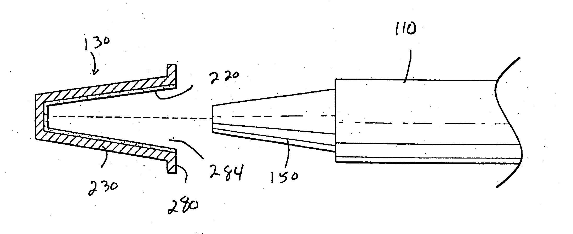
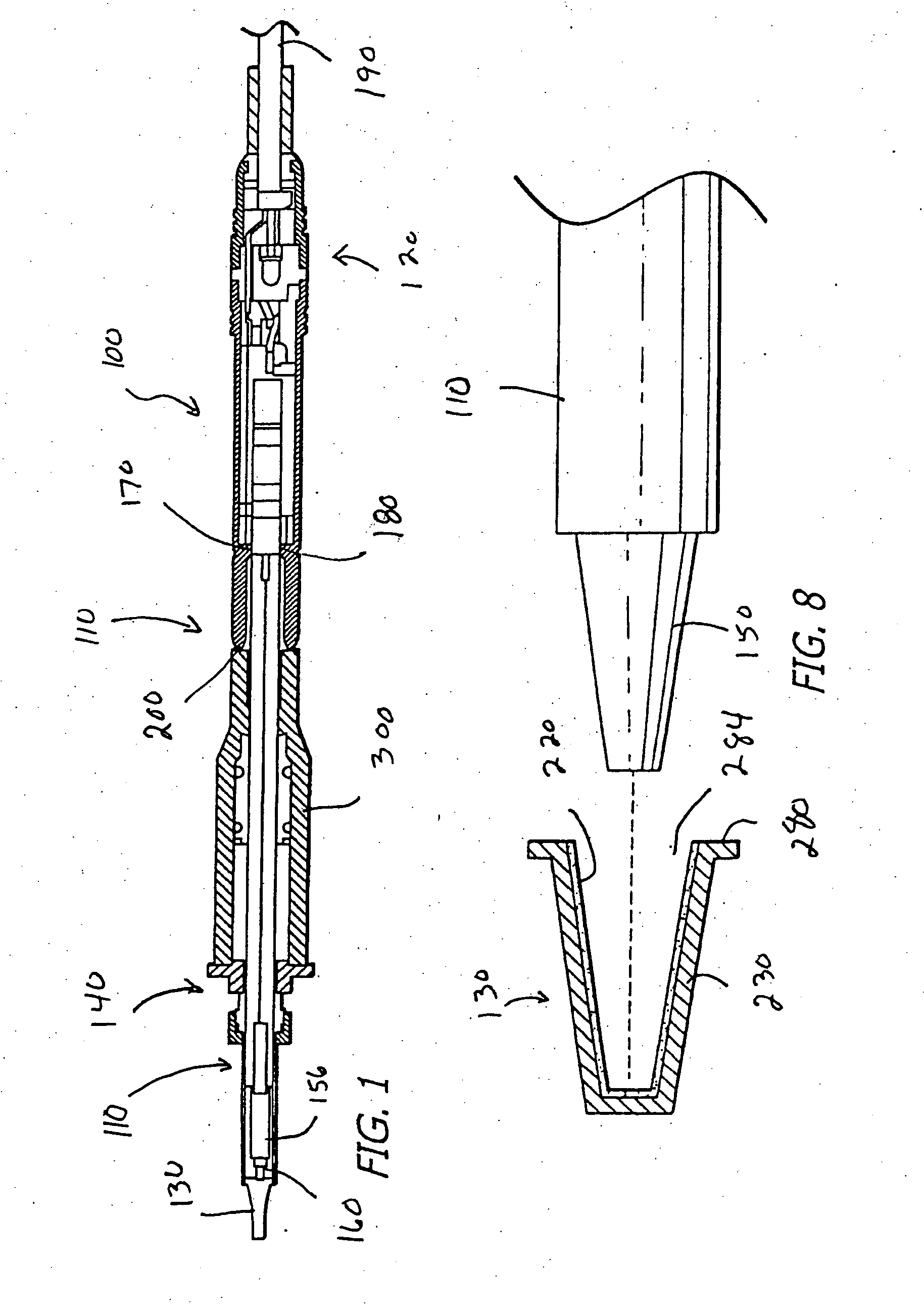
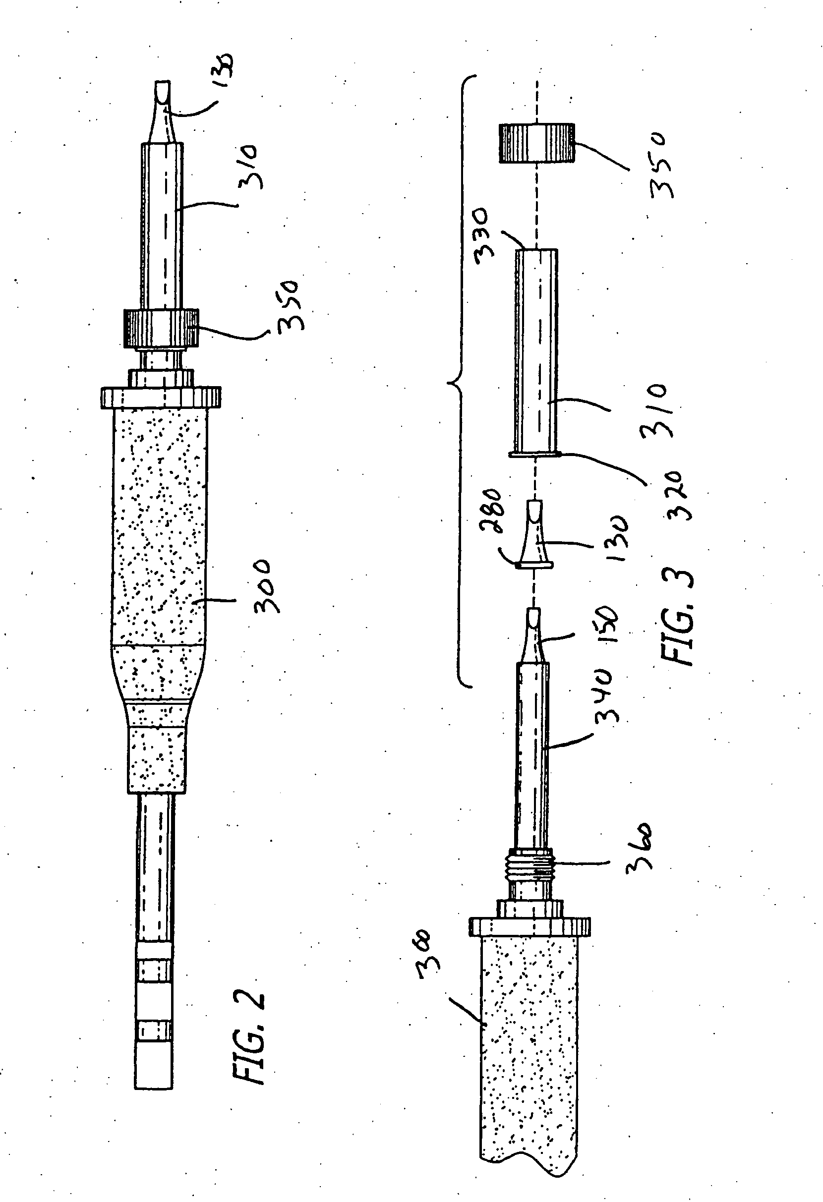
[0049] Referring to FIG. 1, a soldering iron of the present invention is illustrated generally at 100. Soldering iron 100 includes a heating assembly 110 (or heating unit) shown generally at 110, a connector assembly 120, a replaceable soldering iron tip cap 130, and a holding assembly 140 for releasably holding the tip cap 130 on the tapered working tip 150 of the copper or copper alloy 154 of the heating assembly 110. The heating assembly 110 also can include a heating unit 156 and a temperature sensor 160. The heating assembly 110 is removable from the connector assembly 120 for replacement purposes. It is snap fit into the forward end of the connector assembly 120 and held therein, for example, by an O-ring 170. The soldering iron 100 of FIG. 1 and its construction, components and operation, can perhaps better be understood from U.S. application Ser. No. 10 / 264,718, filed Oct. 4, 2002, and entitled “Iron Tip And Electric Soldering Iron” and U.S. application Ser. No. 10 / 686,439, ...


PUM

PropertyMeasurementUnit
melting temperatureaaaaaaaaaa
particle sizeaaaaaaaaaa

Abstract

A soldering iron (and a desoldering iron) with a replaceable tip cap are herein disclosed. The replaceable tip cap is fitted on the forward heat-conducting core end of a soldering (or desoldering) iron heat assembly. Conductive paste, powder or a low melting temperature material such as solder, can be sandwiched between the tip cap and the forward end to improve heat conductivity therebetween. An assembly which allows for the easy removal and application of a replacement tip cap can include a sleeve with tightening bolt, a coil spring sleeve, or a slotted compressible sleeve. The tip cap can thus be replaced after it has worn out, and the heat assembly unit need not be replaced until it has burnt out.

Description

CROSS REFERENCE TO RELATED APPLICATIONS [0001] This is a continuation-in-part of pending application serial no. 10 / 719,001, filed Nov. 21, 2003, which claims the benefit of Japanese Application 2002-342823, filed Nov. 26, 2002, and of International application no. PCT / US _ _ _ _ _ _ , filed May 25, 2004 and entitled “Soldering Iron with Replacable Tip Cap.” The entire contents of all of these applications are hereby incorporated by reference. BACKGROUND OF THE INVENTION [0002] The present invention relates to soldering iron tips for electric soldering tools and for desoldering tools. It further relates to methods of manufacturing and using soldering iron tips. [0003] Soldering is a method for connecting and bonding components to provide secure electrical connections in the electronics industry. Soldering can be roughly classified into two categories, namely, mass soldering (batch soldering) and manual soldering. Mass soldering includes wave or flow soldering wherein electrical eleme...

Claims


Application Information

Patent Timeline
Patent Type & Authority Applications(United States)
IPC IPC(8): B22F7/06B22F7/08B23K3/02B23K3/03
CPCB22F7/064B22F7/08B22F2998/00B23K3/025B23K3/0338B23K3/0361B23K3/0369B23K2203/12B22F3/04B22F3/15B22F9/04B23K2103/12
Inventor UETANI, TAKASHINAGASE, TAKASHIMASAKI, HIROYUKI
Owner HAKKO CO LTD
Why Eureka
Try Eureka