Hybrid natural-fiber composites with cellular skeletal structures

a natural fiber and composite technology, applied in the field of hybrid natural fiber composites with cellular skeletal structures, can solve the problems of limited use of synthetic frp composites in non-primary or non-load-bearing applications, and reduced strength and stiffness

Inactive Publication Date: 2005-01-20
BOARD OF TRUSTEES OPERATING MICHIGAN STATE UNIV
View PDF13 Cites 47 Cited by
  • Summary
  • Abstract
  • Description
  • Claims
  • Application Information

AI Technical Summary

Benefits of technology

It is therefore an object of the present invention to provide novel composites which can be used in load bearing applications, particularly as a replacement for lumber. Further, it is an object of the present invention to provide methods for the preparation of such composites. Further still, it is an object of the present invention to provide composites which are easily and economically fabricated. These and other objects will become increasingly apparent from the following description and the drawings.
The invention provides for the engineering, design, and manufacturing of hybrid 110 cellular 105, 106, 102, 112 nanoreinforced biocomposites, or nano-biocomposites, for structural beams 100 and panels 101. Hybrid cellular nano-biocomposites are defined here for the first time as the enhanced material system obtained by the synergistic combination of a biobased resin reinforced with nano-scale clay particles 110 and natural fibers (or hybrid combination of different natural fibers and / or limited synthetic fibers), and strategically arranged in optimized cellular forms 112 for use as load-bearing, or structural, beams 100 and panels 101. The cellular nano-biocomposite can be used for beam and panel (i.e., plate, or shell) components for multiple use (e.g., building walls, floors and roods, bridge decks, ship top decking, aircraft flooring, wings, etc.) with tailorable integrated multi-functions (i.e., stiffness, strength, toughness, thermal insulation, and user friendliness).

Problems solved by technology

In spite of these advantages, the widespread use of synthetic FRP composites has been limited, among several factors, due to their higher initial material costs, their use in non-efficient structural forms and their environmental impact.
Despite the interest and environmental appeal of biocomposites, their use has been limited to non-primary, or non-load-bearing applications due to their lower strength and stiffness compared with synthetic FRP composites (Biswas et al., “Development of Natural Fibre Composites in India”, Proceedings of the Composites Fabricators Association's Composites, Tampa, Fla.
While biocomposite materials with specific properties equivalent to entry-level structural materials are feasible, this performance level is still not enough to make them able to compete with existing construction materials.
However, the uses in these markets have been limited to non-structural applications where weight and cost can be reduced (Biswas et al., Proceedings of the Composites Fabricators Association's Composites, Tampa, Fla.
Consideration of biocomposites for load-bearing, or structural applications has been neglected due to their low stiffness and strength in comparison with conventional construction materials, and only limited research and development projects have considered potential structural uses (Scott, C. T., et al., Wood and Fiber Science, 27(4): 402-412, (October 1995); and Shenton III, H. W., et al., “Manufacture of Fiber-Reinforced-Foam Composite Sandwich Structures”, Proceedings of the International Conference on Advances in Building Technology, Hong Kong, China (December 2002)).
However, despite the developments on biocomposites technology and the many applications thus far, their lower stiffness and strength properties have limited their applications to non-load-bearing components.
In spite of these achievements, biocomposites are hindered by the hydrophilic nature of the natural fibers and the heat susceptibility of the polymer matrix.
In addition, while the properties of biocomposites can compete with those of E-glass composites, their strength, and particularly stiffness, is smaller than that of conventional structural materials.

Method used


Image

  • Hybrid natural-fiber composites with cellular skeletal structures
  • Hybrid natural-fiber composites with cellular skeletal structures
  • Hybrid natural-fiber composites with cellular skeletal structures

Examples


Embodiment Construction

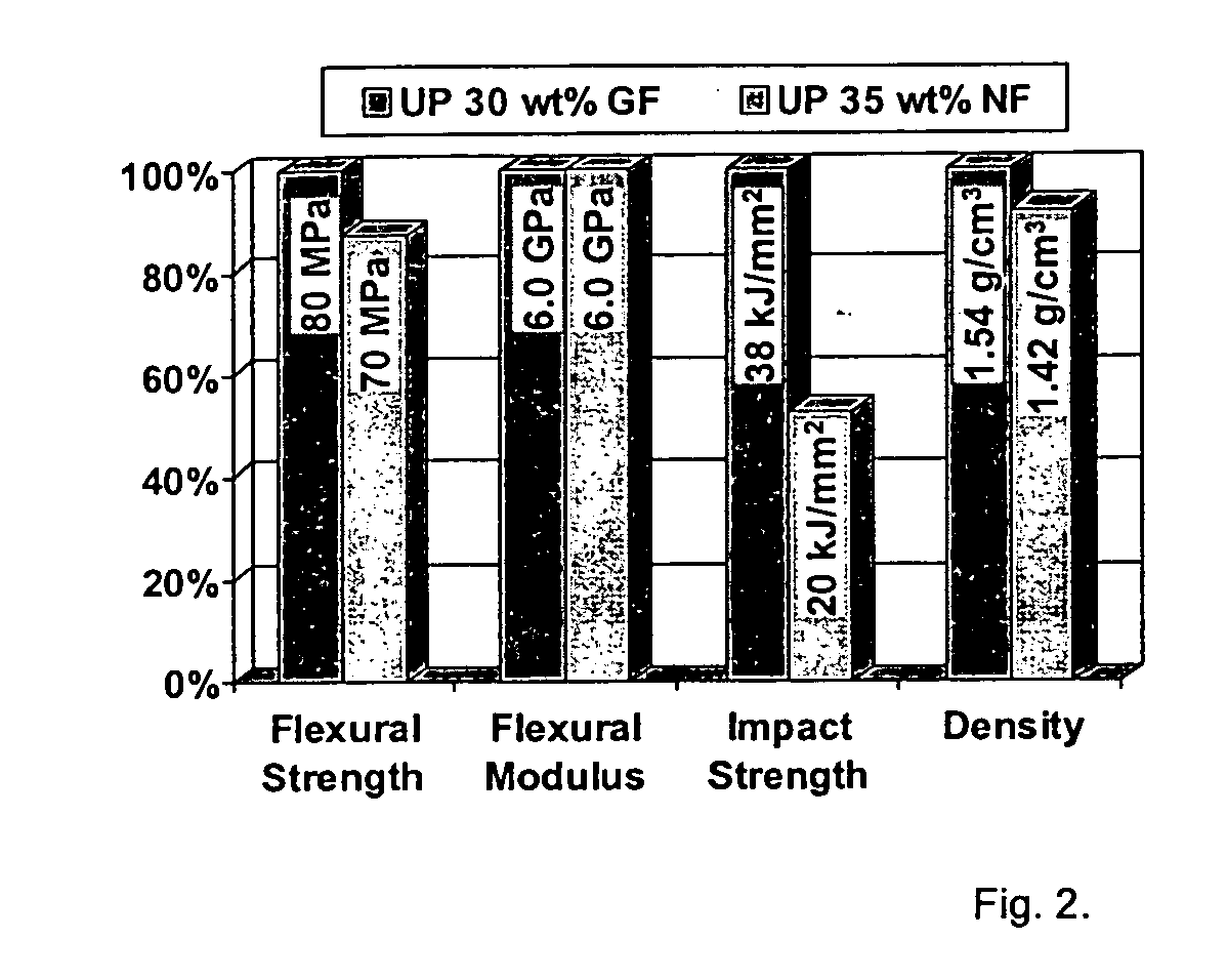
The invention has two main objectives: (a) to establish a minimum database for biocomposite materials to assess their current status and evaluate their feasibility for structural applications, and (b) to provide the necessary material characterization for the material systems used in the structural experimental studies. In addition, hybrid material systems using hemp fibers in combination with chopped E-glass, unidirectional carbon, and weaved jute fabrics were also investigated. In all cases, the resin system consisted of unsaturated polyester resin. The performance of the biocomposite material systems are compared with that of E-glass fiber-reinforced composites.

The macro-scale properties of the material systems were studied through ASTM material testing procedures for short fiber reinforced plastics. The evaluated properties were: tensile strength and modulus (D695), flexural strength and modulus (D790), fracture toughness (D256), thermal expansion (D696), water absorption (D5...


PUM

PropertyMeasurementUnit
volume fractionaaaaaaaaaa
lengthaaaaaaaaaa

Abstract

The present invention relates to composite structural members comprising polymers, natural and synthetic fibers, and nano-scale platelets arranged in two- or three-dimensional cellular skeletal structure; more particularly referring to a low-cost natural-fiber based structural member with material hybridization and material layout for improved behavior that leads to efficient structural beam and plate / panel components that can be used in a plurality of modular structures, resulting in lower cost and reduced environmental impact.

Description

STATEMENT REGARDING FEDERALLY SPONSORED RESEARCH OR DEVELOPMENT Not Applicable BACKGROUND OF THE INVENTION (1) Field of the Invention The present invention relates to composite structural members comprising polymers, natural and synthetic fibers, and preferably nano-scale platelets, arranged in two- or three-dimensional cellular skeletal structure; more particularly referring to a low-cost natural-fiber based structural member with material hybridization and material layout for improved behavior that leads to efficient structural beam and plate / panel components that can be used in a plurality of modular structures, resulting in lower cost and reduced environmental impact. (2) Background of the Invention Fiber reinforced polymer (FRP) composites have surpassed their initial target applications in the aerospace industry to become a viable material alternative in the sporting goods, automotive, and construction industries. High performance FRP composites made with synthetic fibers...

Claims


Application Information

Patent Timeline
Patent Type & Authority Applications(United States)
IPC IPC(8): B32B3/12B32B27/04E04C2/16E04C2/24
CPCB32B3/12E04C2/246E04C2/16B32B27/04Y10T428/249924Y10T428/249932B32B2260/021B32B2260/046B32B2307/732
Inventor BURGUENO, RIGOBERTOMOHANTY, AMAR K.QUAGLIATA, MARIO JOHN
Owner BOARD OF TRUSTEES OPERATING MICHIGAN STATE UNIV
Why Eureka
Try Eureka