
Hybrid inflator

a hybrid inflator and inflator technology, applied in the direction of pedestrian/occupant safety arrangement, vehicle components, chemistry apparatus and processes, etc., can solve the problems of increasing the pressure inside the inflator, burning of remaining unburnt gas generating agent, difficulty in burning gas generating agent, etc., to improve the combustibility, improve the safety of work, and improve the effect of delay

Inactive Publication Date: 2005-01-27
DAICEL CHEM IND LTD
View PDF3 Cites 10 Cited by
  • Summary
  • Abstract
  • Description
  • Claims
  • Application Information

AI Technical Summary

Benefits of technology

A problem to be solved is, with a hybrid inflator in which are provided plural combustion chambers each having a gas generating agent therein, to increase the pressure inside the inflator housing when ignition and burning are carried out after a delay, thus improving the gas generating agent combustion performance, and hence suppressing the production of gases such as CO and NOx.
According to the hybrid inflator of the present invention, when, out of the two combustion chambers, only the gas generating agent in one of the combustion chambers is burnt as air bag inflation means, and then to secure the safety of work during disposing of the motor vehicle, the gas generating agent in the other combustion chamber is burnt after a delay of approximately 100 milliseconds from the commencement of the burning of the first gas generating agent, the combustibility of the gas generating agent burnt after the delay is improved. In particular, with the present invention, the combustibility can be improved merely by shielding some of the communication holes with a shielding means, and hence the present invention is excellent in that a large effect is obtained through simple means, and moreover can also be used as means for improving the combustibility with an existing hybrid inflator.

Problems solved by technology

Furthermore, if the collision of the motor vehicle is light, and hence the impact to which the passenger is subjected is light, the air bag may be inflated by burning only one of the gas generating agents, but even in this case, in consideration of the safety of work when subsequently disposing of the motor vehicle, the remaining unburnt gas generating agent is also burnt, with this being unrelated to the inflation of the air bag to protect the passenger.
In general, the burning rate of a gas generating agent tends to be higher, the higher the pressure is, and hence in the above case it becomes that the gas generating agent burns with difficulty.
Furthermore, when the burning of the unburnt gas generating agent is commenced and hence high-temperature combustion gas is generated, the pressure inside the inflator increases somewhat; however, openings of the hybrid inflator (gas discharge ports and an opening portion near thereto) are set to have an opening size (opening area) for the state in which the pressurized medium is present inside, and thus the opening area is too large relative to the total surface area of the unburnt gas generating agent, and hence the internal pressure is not increased to an extent that the burning of the gas generating agent is promoted well.
In the case that the unburnt gas generating agent is burnt under atmospheric pressure in this way, the burning time may be too long, and gas components such as CO and NOx may be generated due to the insufficient pressure.
Consequently, with this art, the problem described above does not arise, but on the other hand there are problems predominantly in terms of manufacture in that a double structure of the first chamber and the second chamber must be adopted, the first chamber and the second chamber must be separately closed off with rupturable plates, and a long time is required for the pressures in the first chamber and the second chamber to be equalized.
It is thought that if such a thick rupturable plate is used, then when the first chamber and the second chamber are actuated simultaneously, the rupturable plate of the second chamber will rupture with difficulty, and hence it will become necessary to install an igniter having a very large output in the second chamber.
In this state, after most of the pressurized medium has been discharged, the inside of the housing is in a state close to atmospheric pressure, and hence the pressure is insufficient when the unburnt gas generating agent is consumed, causing the production of gases such as CO and NOx.

Method used


Image

  • Hybrid inflator
  • Hybrid inflator
  • Hybrid inflator

Examples


example 1

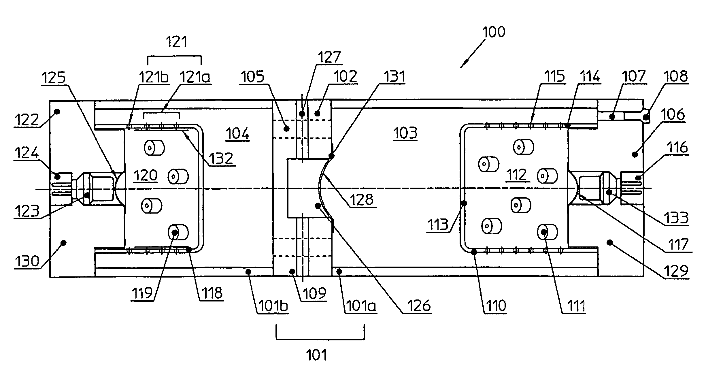
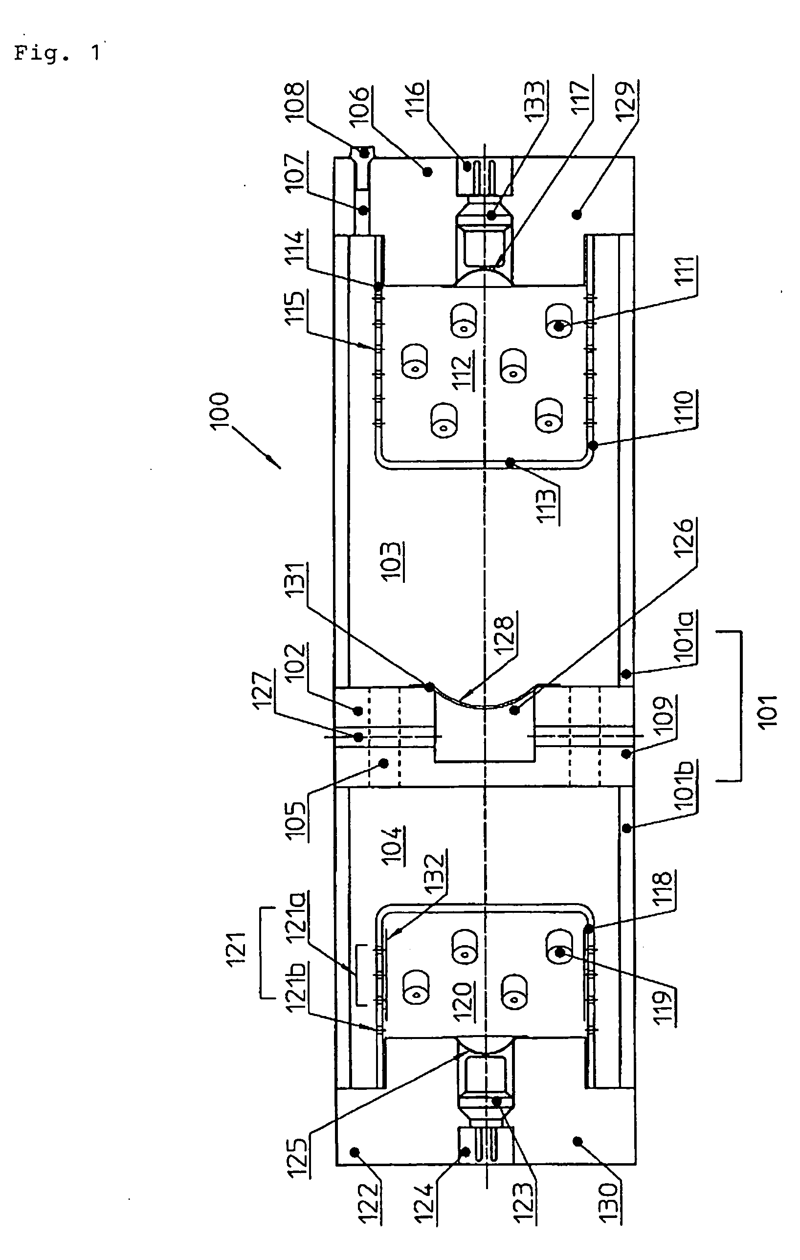
A hybrid inflator as shown in FIG. 1 was manufactured. The details of the various elements were as follows. Composition of gas generating agent: Nitroguanidine / strontium nitrate / carboxymethyl cellulose Na salt / acid clay=34:50:9:7 (proportions by mass) Amounts of gas generating agents: 20 g of above gas generating agent used as each of first gas generating agent and second gas generating agent (total 40 g, corresponding to 1 mol of generated gas; pressure index 0.6) Shape of gas generating agents: Cylinder with single hole (through hole), outside diameter 5 mm, inside diameter 1.2 mm, length 5 mm Surface area of first gas generating agent (S1): 13,700 mm2 Surface area of second gas generating agent (S2): 13,700 mm2 Pressurized medium: 2.6 mol (100 g) of mixed gas with argon:helium=96:4 (molar ratio) Charging pressure of pressurized medium: 32,000 kPa A1st (total area of first openings): 120 mm2 A2nd−1 (total area of non-shielded open second openings): 17.0 mm2 A2nd−2 (tota...


PUM


Abstract

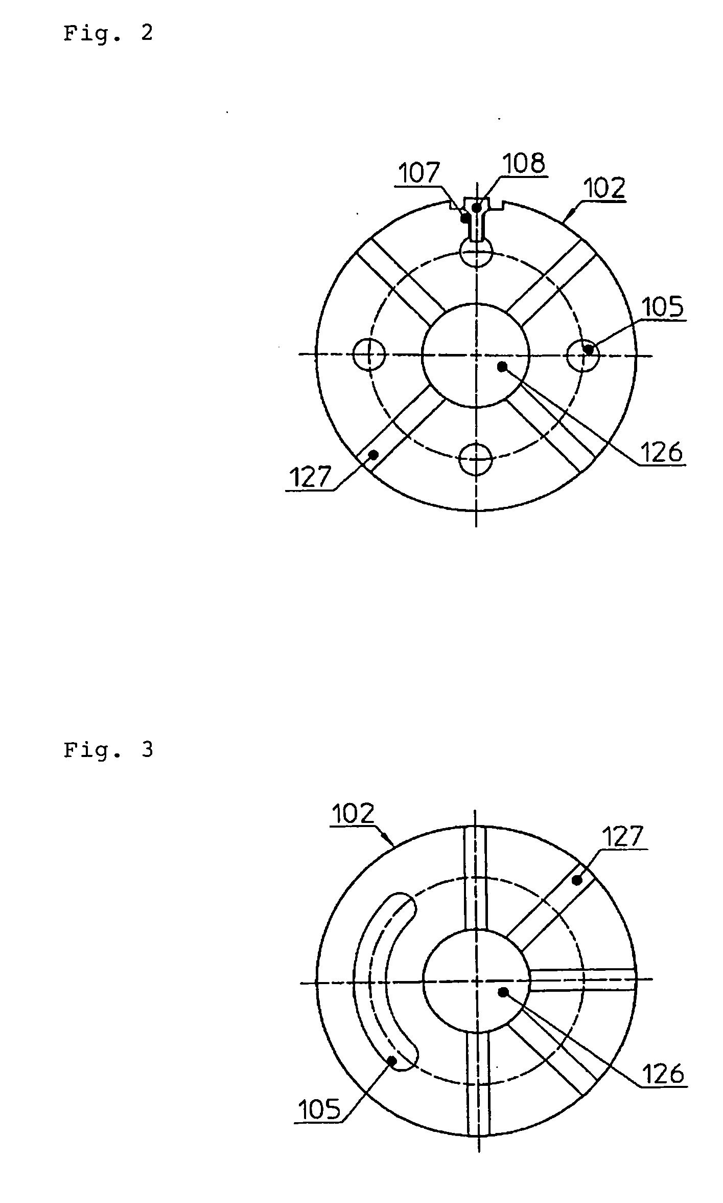
To provide a hybrid inflator in which the combustibility of a second gas generating agent is improved. Some of the openings 121a out of second openings 121 are shielded with tape 132, and the opening area A2nd−1 of the remaining openings and the opening area Aex of an opening portion 131 of a recessed portion of a partition member for controlling an outflow pressure of gas satisfy the relationship Aex>A2nd−1, whereby the pressure inside a second combustion chamber 120 readily rises upon burning the second gas generating agent 119. The combustibility of the second gas generating agent 119 is thus favorable even when a pressurized medium has been discharged and hence the internal pressure has become equal to atmospheric pressure.

Description

TECHNICAL FIELD The present invention relates to a hybrid inflator suitable for use in an air bag system installed in a motor vehicle, and such an air bag system. PRIOR ART With a dual type hybrid inflator having two combustion chambers, the gas generating agents housed in the two combustion chambers are set to be burnt either simultaneously or with one delayed in accordance with the degree of impact to which a passenger is subjected upon collision of a motor vehicle. Furthermore, if the collision of the motor vehicle is light, and hence the impact to which the passenger is subjected is light, the air bag may be inflated by burning only one of the gas generating agents, but even in this case, in consideration of the safety of work when subsequently disposing of the motor vehicle, the remaining unburnt gas generating agent is also burnt, with this being unrelated to the inflation of the air bag to protect the passenger. This burning of the unburnt gas generating agent is commenced...

Claims


Application Information

Patent Timeline
IPC IPC(8): B01J7/00B60R21/26B60R21/263B60R21/272
CPCB60R21/261B60R2021/2685B60R21/272
Inventor YAMAZAKI, MASAYUKI
Owner DAICEL CHEM IND LTD
Learn More