Hydro-power generating system

a technology of hydro-power generation and generating system, which is applied in the direction of electric generator control, machines/engines, mechanical equipment, etc., can solve the problems of loss of traditional lands, loss of habitat, loss of both land and water, and slowing of earth's axial rotation, so as to reduce the likelihood, and increase the speed of moving water

Inactive Publication Date: 2005-01-27
SIPP PETER FOX
View PDF46 Cites 50 Cited by
  • Summary
  • Abstract
  • Description
  • Claims
  • Application Information

AI Technical Summary

Benefits of technology

[0017] It is also preferred that the rigid structure is raisable and rotatable so that the wheel assembly may be removed from the moving water. In addition, it is preferred that a screen is provided and adapted to be located in close proximity to, but upstream from, the wheel assembly. The screen permits water to readily pass there through and reduces the likelihood that debris will interfere with the rotatable wheel.
[0018] It is also preferred that a funnel assembly be placed adjacent to the wheel assembly. The funnel assembly is for increasing the speed of the moving water as the moving water contacts the rotatable drum.
[0019] In accordance with another form of the invention, there is provided a hydro-power generating system, including a wheel assembly having at least one rotatable wheel. The rotatable wheel is adapted to interface with moving water. The rotatable wheel rotates when contacted by moving water, th

Problems solved by technology

While in the past century large dams were erected to maximize the kinetic potential of freshwater, these have proved to have consequences that are not always beneficial, including loss of traditional lands, loss and disruption of habitat, both land and aquatic, and even repor

Method used


Image

  • Hydro-power generating system
  • Hydro-power generating system
  • Hydro-power generating system

Examples


Embodiment Construction

Overview

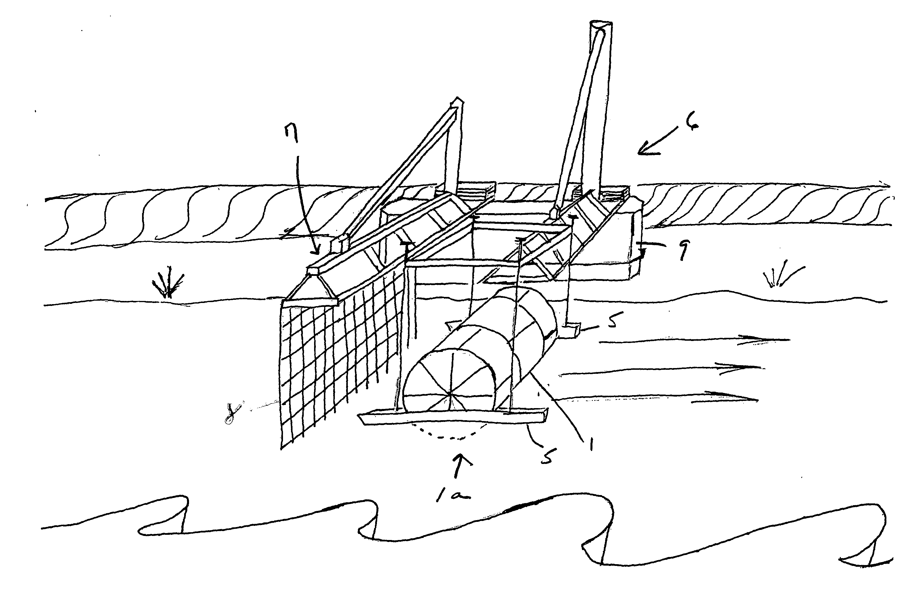
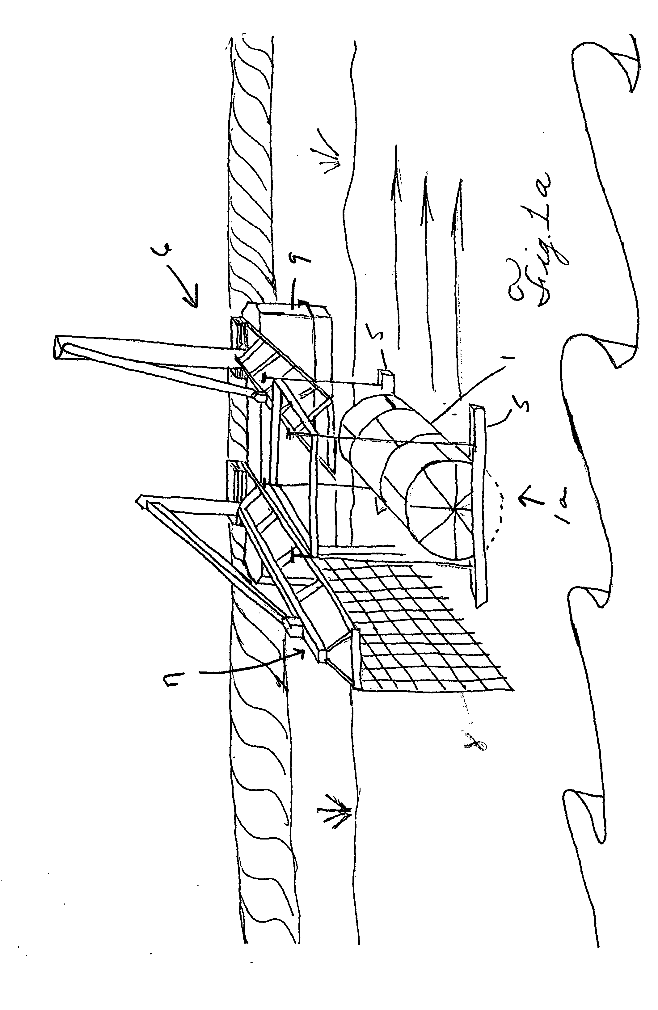
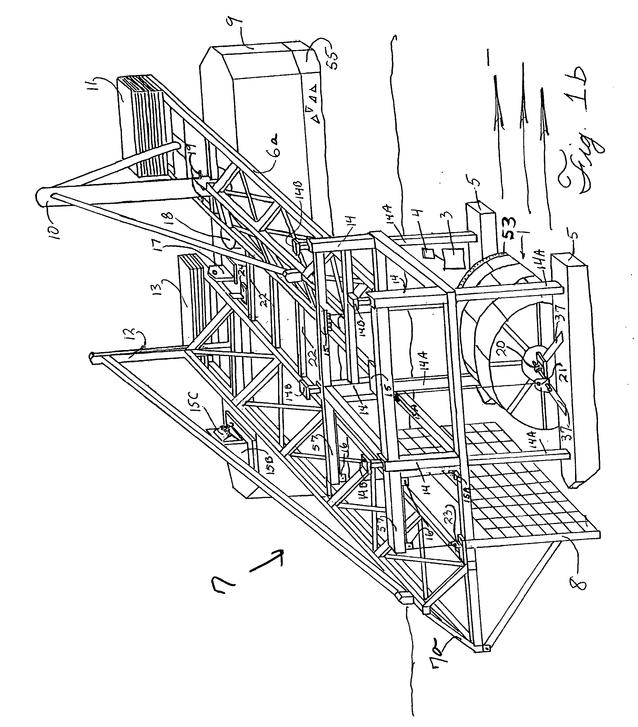
[0045] The invention is a unique array of classical elements which, when combined, generate electricity or direct mechanical power from the moving water without a dam or other substantial diversion of the water. The system enables the generating station to be rapidly removed in the event of flood or other seasonal changes and for services to be performed.

[0046] The system may include: an anchor with service hull, a jib crane, a water wheel floating on pontoons, a drawbridge, a screen, a speed increaser, and one or more generators, or, in the case of mechanical power generation, a pump and one or more shafts. This overview will focus on electrical generation.

[0047] Electricity is generated by the rotation of a large diameter, wide-bladed wheel, or a plurality of wheels, pushed at the bottom by the flow of water, with the axel supported by pontoons. The slow turning of the wheel is translated into electrical power by the use of a speed increaser and generator(s) {or alterna...


PUM


Abstract

There is provided a hydro-power generating system including a wheel assembly having at least one rotatable wheel. The rotatable wheel is adapted to interface with moving water. The rotatable wheel rotates when contacting moving water, thereby generating power. An elongated rigid structure is provided with at least a portion thereof located above the rotatable wheel. The elongated rigid structure is secured so that the moving water will not cause the elongated rigid structure to move substantially. The wheel assembly includes at least one floatation member wherein the rotatable wheel will only be partially submerged in the moving water. The wheel assembly is connected to the elongated rigid structure so that the wheel assembly is held in place in the moving water. The wheel assembly is slidably connected to the elongated rigid structure so that the rotatable wheel may move vertically as the level of the moving water changes. A funnel and a screen are situated adjacent to and upstream of the wheel assembly.

Description

[0001] This invention relates to systems for generating power, such as electrical power. More specifically, it relates to hydro-power generating systems which do not rely on dams. BACKGROUND OF THE INVENTION [0002] Some of the greatest challenges facing humanity today stem from the by products of energy generation and utilization. Carbon dioxide, sulfur, radioactive waste and other wastes and emissions challenge both human and environmental health and economic profitability of fossil and nuclear energy, making sustainable energy generation not only a preferred “alternative,” but also, a necessity. While wind powered generation, worldwide, is the fastest growing form of new generating capacity, it, and solar, are intermittent generating sources. Hydroelectric generation has long stood as a reliable, constant source of renewable power generation that produces no waste or emissions. [0003] The sun's energy and Earth's gravity provide the sustaining cycle for freshwater hydro-mechanical...

Claims


Application Information

Patent Timeline
IPC IPC(8): F03B13/00F03B17/06H02P9/04
CPCF03B17/063Y02E10/28F05B2240/932F05B2240/93Y02E10/30Y02E10/20
Inventor SIPP, PETER FOX
Owner SIPP PETER FOX
Why Eureka
Try Eureka