Multilayer barrier film structure and organic electroluminescent display panel and manufacturing method thereof

Inactive Publication Date: 2005-01-27
PIONEER CORP
View PDF7 Cites 94 Cited by
  • Summary
  • Abstract
  • Description
  • Claims
  • Application Information

AI Technical Summary

Benefits of technology

[0009] A problem to be solved by the present invention is to provide a multilayer barrier film structure having high gas barrier ability, and an organic E

Problems solved by technology

There is a problem that if such an organic EL device is exposed to the atmosphere, then the organic EL device is affected by infiltration of molecules of oxygen, water and the like, and hence there is a marked deterioration in light emission characteristics such as brightness and color.
The gas barrier ability of a multilayer gas barrier film is affected by the gas barrier ability of each film itself, and is also greatly affected by the density of defects such as pinholes.
However, the inorganic films are formed using a dry film formation method such as vacuum deposition or sputtering, and hence local defects such as pinholes are prone to occur.
However, even with a multilayer gas barrier film, if all of the layers are formed using a dry film formation method

Method used


Image

  • Multilayer barrier film structure and organic electroluminescent display panel and manufacturing method thereof
  • Multilayer barrier film structure and organic electroluminescent display panel and manufacturing method thereof
  • Multilayer barrier film structure and organic electroluminescent display panel and manufacturing method thereof

Examples


Example

[0029] Following is a description of embodiments of the present invention, with reference to the drawings.

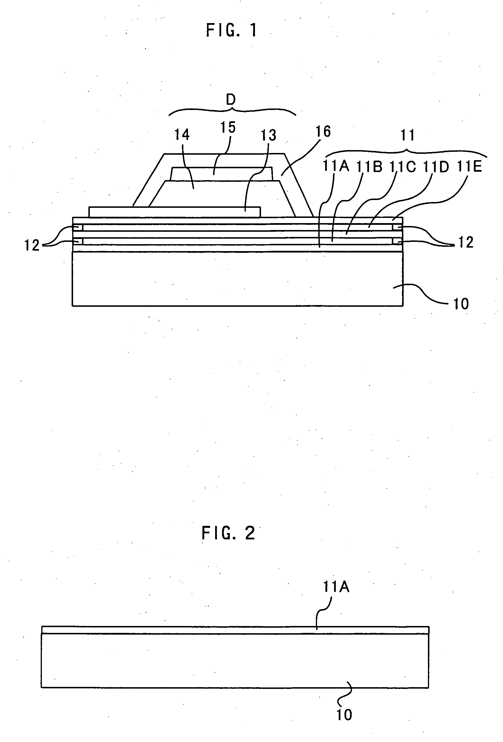
[0030]FIG. 1 shows one of a plurality of organic EL devices in an organic EL display panel having a multilayer barrier film structure according to an embodiment of the present invention.

[0031] In the organic EL device D, for example, a transparent electrode (first display electrode) 13 made of indium tin oxide (ITO) is formed by vapor deposition, sputtering or the like on a multilayered body 11 on a transparent supporting substrate 10.

[0032] On the transparent electrode 13, for example, a hole injection layer made of copper phthalocyanine, a hole transport layer made of TPD (a triphenylamine derivative), a light-emitting layer made of Alq3 (an aluminum chelate complex), and an electron injection layer made of Li2O (lithium oxide) are formed in this order by vapor deposition; these layers constitute an organic functional layer 14. Furthermore, a metal electrode (second display...


PUM


Abstract

A multilayer barrier film structure of an organic. EL display panel has a multilayered body formed on a surface of a supporting substrate. The multilayered body includes an intermediate film for which the number of molecules of oxygen, water and the like permeating through is reduced upon heating or irradiation and inorganic films formed so as to sandwich the intermediate film. The film structure includes a sealing region where the intermediate film has been transformed by heating or irradiation provided so as to surround the multilayered body on the surface of the supporting substrate. In a method of manufacturing an organic EL display panel comprising an organic EL device and a supporting substrate supporting the organic EL device, a first inorganic film is formed so as to cover a surface of a supporting substrate, an intermediate film for which the number of molecules of oxygen, water and the like permeating through is reduced upon heating or irradiation is formed on the first inorganic film, a second inorganic film is formed on the intermediate film, an organic EL device comprising first and second display electrodes and at least one organic functional layer comprising an organic compound formed so as to be sandwiched between the first and second display electrodes is formed on the second inorganic film, and a perimeter outside the organic EL device is subjected to heating or irradiation, to form a sealing region where the intermediate film has been transformed surrounding the organic EL device.

Description

BACKGROUND OF THE INVENTION [0001] 1. Field of the Invention [0002] The present invention relates to a multilayer barrier film structure, and an organic electroluminescent display panel and a manufacturing method thereof. [0003] 2. Description of the Related Art [0004] Organic electroluminescent display panels (hereinafter referred to as “organic EL display panels”) in which a plurality of organic electroluminescent devices (hereinafter referred to as “organic EL devices”) are formed on a supporting substrate have been developed to be used in display apparatuses. [0005] An organic EL device is a luminescent device comprising at least one thin film (hereinafter referred to as the “organic functional layer”) including a light-emitting layer made of an organic material that is electroluminescent, i.e., emits light upon an electrical current being injected therein. With such an organic EL device, basically, the organic functional layer is sandwiched between an anode and a cathode, excit...

Claims


Application Information

Patent Timeline
IPC IPC(8): H01L51/50H01L51/52H05B33/02H05B33/04H05B33/10H05B33/14H05B33/22
CPCH01L51/5237H05B33/04Y10S428/917H05B33/22H05B33/145H10K50/8445H10K71/851
Inventor MIYADERA, TOSHIYUKI
Owner PIONEER CORP
Why Eureka
Try Eureka