Media transmitting method, media receiving method, media transmitter and media receiver

a technology of media receiving and transmitting methods, applied in the field of media transmitting methods, media receiving methods, media transmitters and media receivers, can solve problems such as affecting the efficiency of program distribution, affecting the efficiency of program data restoration, and possible packet loss, so as to achieve efficiency and excellence in error resistan

Inactive Publication Date: 2005-01-27
PANASONIC CORP
View PDF7 Cites 48 Cited by
  • Summary
  • Abstract
  • Description
  • Claims
  • Application Information

AI Technical Summary

Benefits of technology

[0032] As described above, according to the invention, a content can be sent with efficiency and excellence in error resistance by using a communication or broadcast network

Problems solved by technology

However, in case the conventional broadcast network scheme is directly applied onto the IP network, there is difficulty in efficiently distributing the programs.
Meanwhile, on the IP network, packet loss possibly takes place due to transmission congestion or errors, which disables program data restoration at the reception end.
However, in the conventional configuration, there is a problem in concerned with header compression that, in the case a plurality of programs or contents (not only medias such as program configuring data, video images, sound and texts but also include

Method used


Image

  • Media transmitting method, media receiving method, media transmitter and media receiver
  • Media transmitting method, media receiving method, media transmitter and media receiver
  • Media transmitting method, media receiving method, media transmitter and media receiver

Examples


first exemplary embodiment

[0058] (First Exemplary Embodiment)

first embodiment

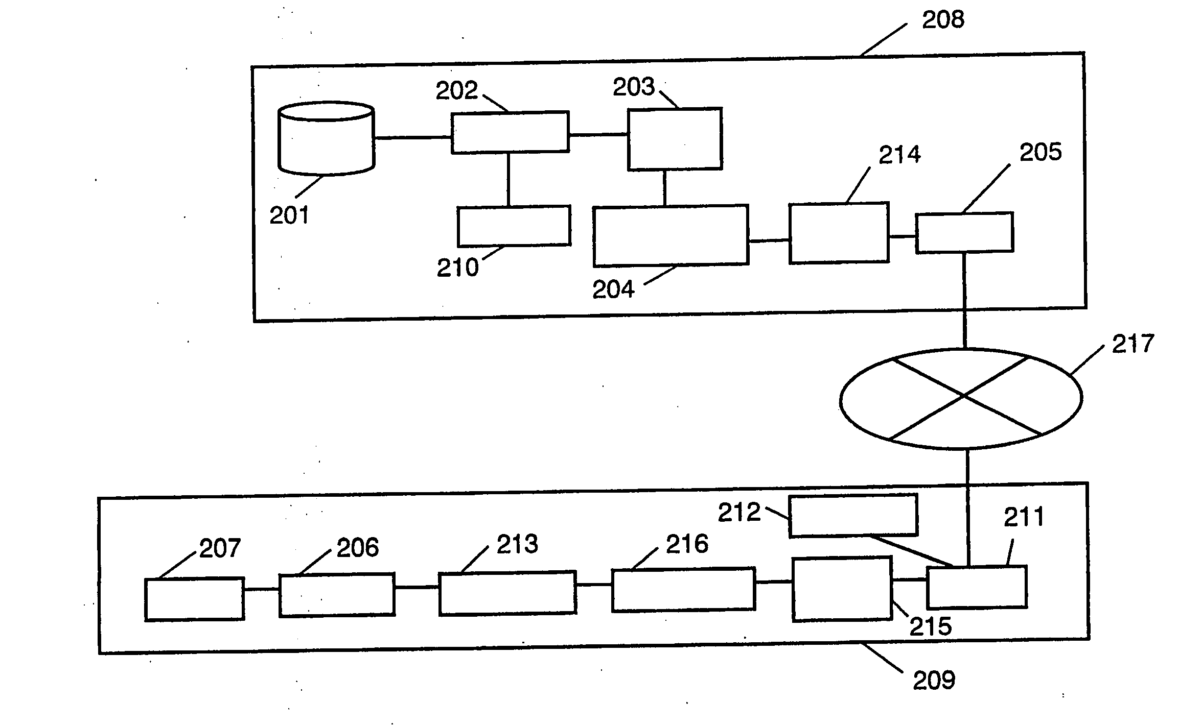
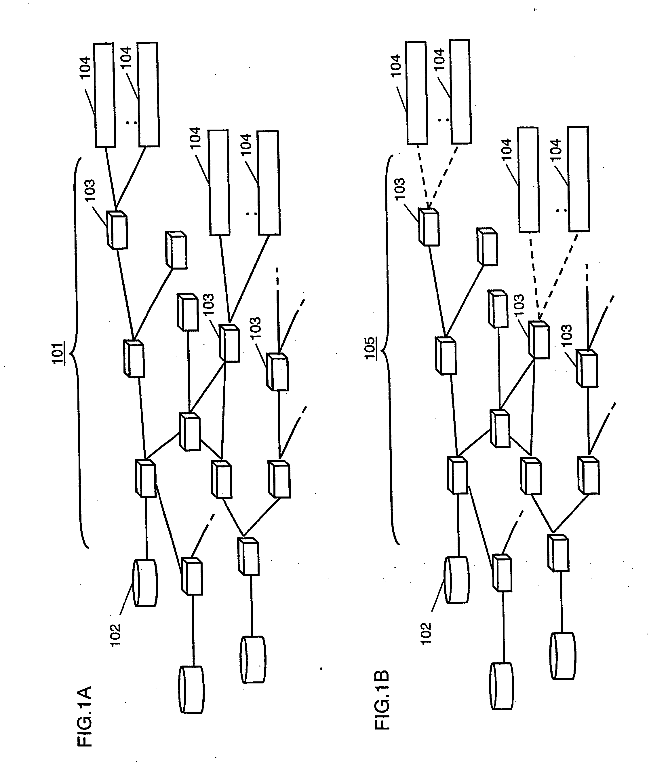
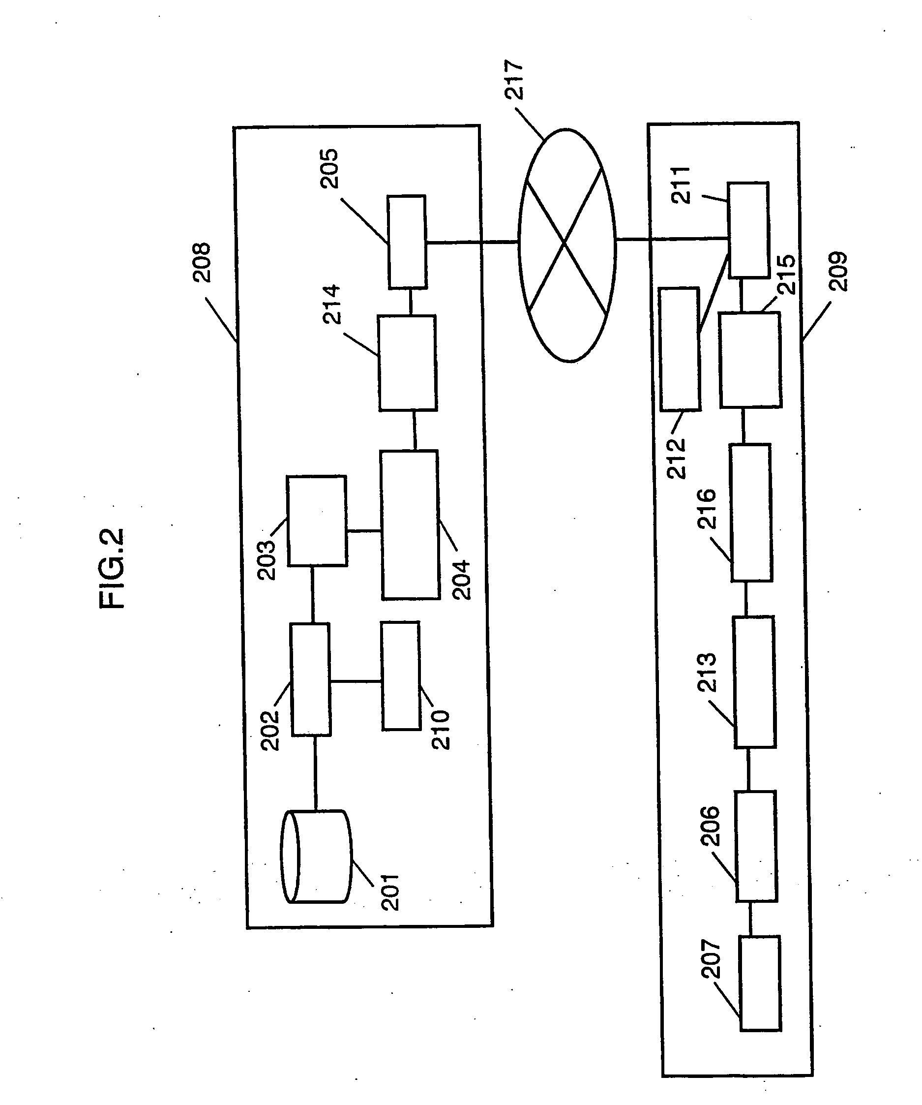
[0059]FIGS. 1A and 1B show a utilization form of a communication network in the invention.

[0060] In FIG. 1A, servers 102 are media transmitters of the invention while terminal units 104 are media receivers of the invention. Meanwhile, a network 101 may be a wired network (e.g. ADSL, ISDN, ATM or FTTH) or a wireless network (e.g. cellular phone or radio RAN). In FIG. 1B, although the configuration is by a wired network at from the server 102 to the relay node 103 and by a wireless network therefrom to the reception terminal unit 104, it may be a communication network 105 interconnected with such wired and wireless networks. The transmission protocol uses an Internet protocol, while communication units are mutually connected by relay nodes 103, such as refuters and GWs (gateways). The routers and GWs have a broadcast or multicast function so that a data packet can be duplicated at the router and GW.

[0061] Also, the content transmitting method may use 1-to-1 communication at between t...

second exemplary embodiment

[0182] (Second Exemplary Embodiment)

[0183] The present embodiment is different from the first embodiment in respect of the program information to be sent from the media transmitter to the media receiver and of the header data structure of media data.

[0184]FIG. 13B is a figure showing a data structure of the header of media data in this embodiment.

[0185] In FIG. 13B, by RTP extension, the lower order 2 bits in the time stamp is provided as bit flags 1303, 1304 of repeated start and end packets. This allows the media receiver to know the start-edge and end-edge packets of a content repeatedly sent, similarly to the first embodiment.

[0186] On the other hand, the program structure, not extended, remains in the conventional data structure shown in FIG. 11A.

[0187] These pieces of information and content data are data-compressed in the media transmitter 208 and interleave-processed, being sent to the media receiver in a repeated fashion.

[0188] The media receiver 208 is different from ...


PUM


Abstract

Provided is a content classifying section 203 for classifying and bundling to-be-transmitted contents on the basis of any piece of information of media kind, IP address, port number and session identifier. A packet header compressing section 204 carries out header compression on the transmission packet. Due to this, because contents can be packet-transferred with efficiency and excellent error resistance by the use of a communication and broadcast network, it is possible to realize, even on the Internet for broadcast in a broadcast form, a quality broadcast free of image or sound discontinuity as the terrestrial-wave TV broadcast.

Description

TECHNICAL FIELD [0001] This invention relates to a media transmitting method, media receiving method, media transmitter and media receiver, for packet-transmitting contents through using a communication or broadcast network. BACKGROUND ART [0002] Conventionally, in media transmission, where providing the same program over to a multiplicity of viewers, efficiency is greater with broadcast-type distribution as represented by terrestrial-wave broadcast than one-to-one communication-type distribution, in respect of saving transmission band. Also, besides simultaneous reproduction of video images and audio sound, it is a practice to control and reproduce on-screen arrangement and reproducing timing of medias including texts, still images and animations. As for a system for reproducing such a plurality of medias, there is a proposal described in W098 / 06222, for example. [0003]FIG. 17 is a configuration diagram of a conventional image decoding / encoding apparatus. [0004] In FIG. 17, the dec...

Claims


Application Information

Patent Timeline
IPC IPC(8): G06F21/10H04L12/18H04L12/70H04L29/06H04N7/173H04N21/226H04N21/2362H04N21/238H04N21/845
CPCH04L12/1881H04L29/06H04L29/06027H04L47/10H04L47/15H04L47/2441H04L69/22H04N21/2381H04N21/44209H04N21/4425H04N21/64322H04L65/607H04L69/04H04L47/38H04L65/70H04L9/40H04L65/1101
Inventor ITOH, TOMOAKIYAMAGUCHI, TAKAOTAKEI, ICHIROMATSUI, YOSHINORINOTOYA, YOUJI
Owner PANASONIC CORP
Why Eureka
Try Eureka