
Spark plug with noble metal chip joined by unique laser welding and fabrication method thereof

a noble metal chip and laser welding technology, applied in spark plug manufacturing, spark plugs, spark plugs, etc., can solve the problems of noble metal chip being removed, noble metal chips being oxidized/volatilized, unfused area in the interface between noble metal chips, etc., to reduce the sectional area b, and increase the reliability of the joint

Active Publication Date: 2005-02-03
DENSO CORP
View PDF2 Cites 37 Cited by
  • Summary
  • Abstract
  • Description
  • Claims
  • Application Information

AI Technical Summary

Benefits of technology

[0018] It is another object of the invention to provide a structure of a spark plug designed to improve the reliability of a weld of a noble metal chip to a ground electrode without sacrificing the productivity of the spark plug and also provide a fabrication method thereof.
[0034] The angle θ1, as described above, represents a range within which the metal shell will be an obstruction to the traveling of the laser beams after the ground electrode is installed on the metal shell, but before the ground electrode is bent. The laser beams are emitted outside the angle θ1 without any optical interference with the metal shell. This permits the angle between the orientation of each of the laser beams and the center electrode-opposed surface to be minimized regardless of the metal shell, thus ensuring a desired depth of the fused portions in the noble metal chip.

Problems solved by technology

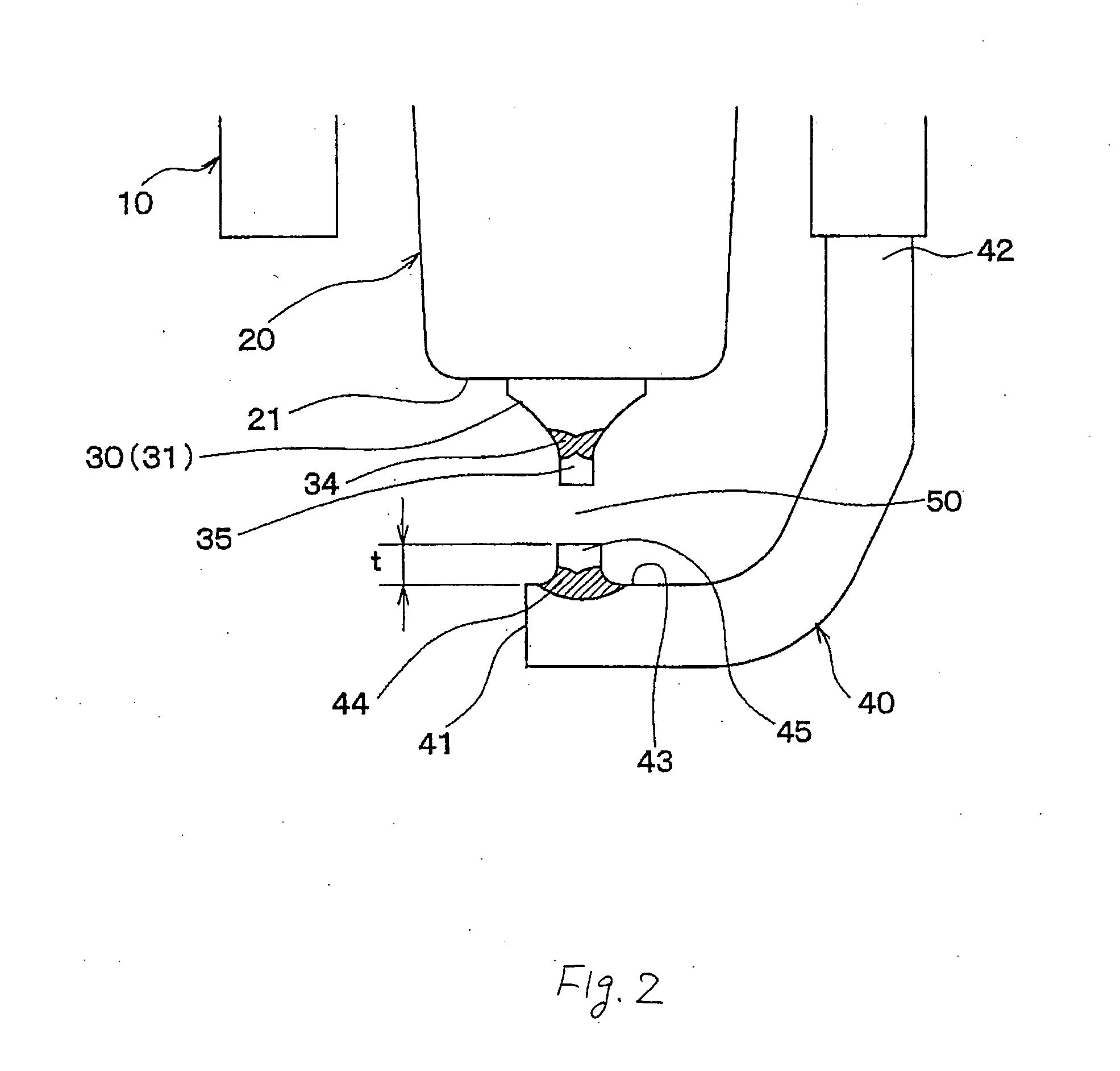
The increased radiation angle θL, however, will result in a decrease in depth DW of a portion of the noble metal chip 45 which is fused by the laser beam LZ into the ground electrode 40 in a radius direction of the noble metal chip 45, thus leading to an undesirable increase in unfused area in the interface between the noble metal chip 45 and the ground electrode 40.
The electrodes, therefore, undergo a thermal stress and oxidation, which may cause the noble metal chips to be removed from the center and ground electrodes.
Particularly, such a problem is exacerbated in the ground electrode because it is exposed to a combustion chamber of the engine more than the center electrode.
The laser welding, as taught in the latter publication, has the drawback in that the metal shell will be an obstruction to the traveling of the laser beams, thus resulting in a difficulty in welding the entire circumference of the interface between the noble metal chip 45 and the ground electrode 40.
Such assembling process, however, results in decreased productivity of the spark plug.
Specifically, the noble metal chip 45 installed on the ground electrode 40 obstructs the welding of the ground electrode 40 to the metal shell, which will lead to an increase in production cost of the spark plug.

Method used


Image

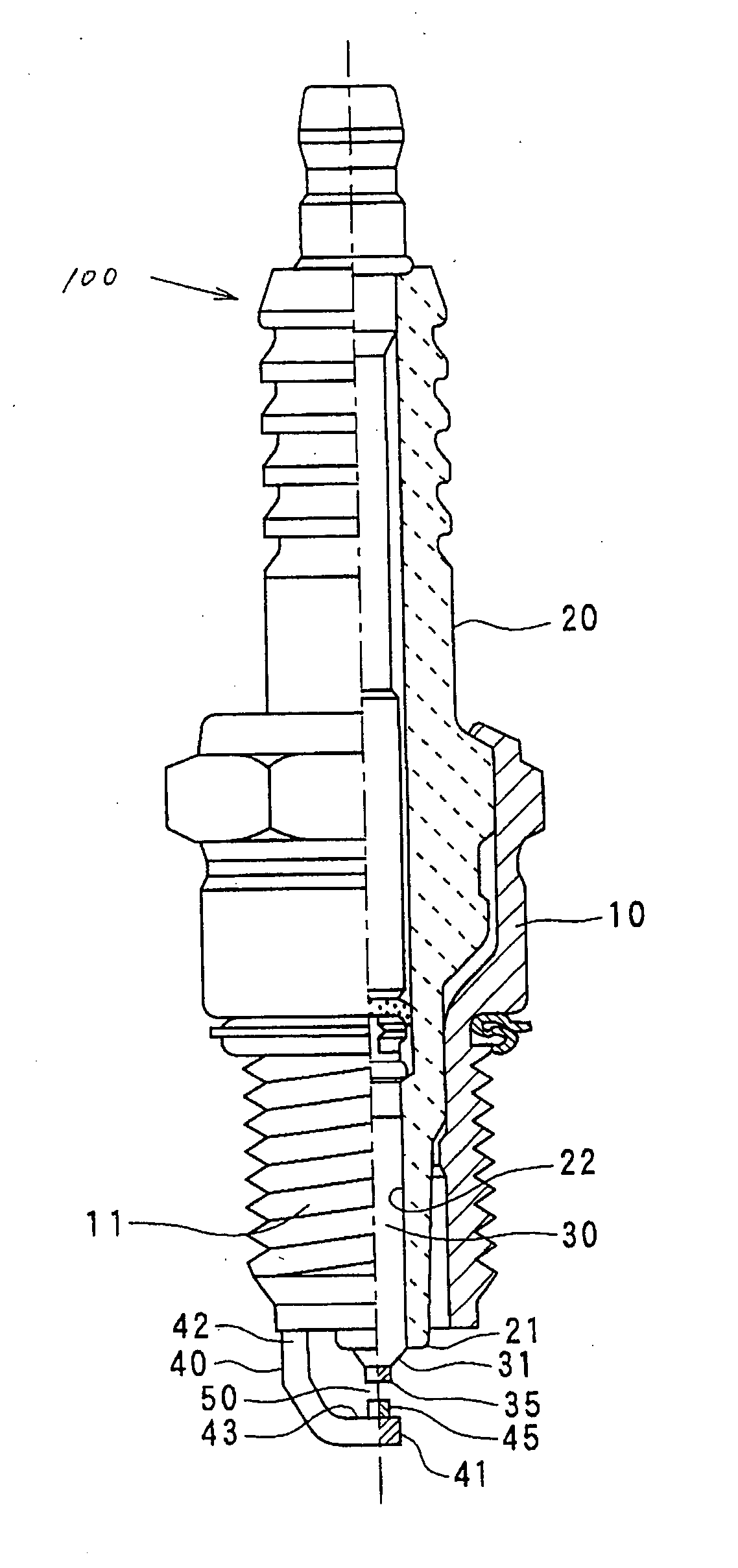
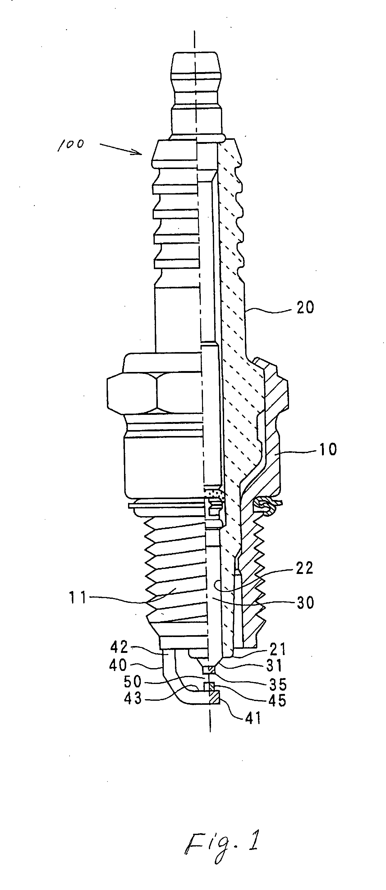
  • Spark plug with noble metal chip joined by unique laser welding and fabrication method thereof
  • Spark plug with noble metal chip joined by unique laser welding and fabrication method thereof
  • Spark plug with noble metal chip joined by unique laser welding and fabrication method thereof

Examples


second embodiment

[0168]FIG. 10 is a top view which shows the noble metal chip 45 which is placed on the inner side surface 43 of the ground electrode 40 before bent and which is subjected to laser welding in the

first embodiment

[0169] In the drawing, “LZ” indicates, like the first embodiment, both the laser radiation path along which the laser beam travels and the laser path projected line defined by projecting the laser radiation path onto a plane extending over the inner side surface 43 of the ground electrode 40 before bent. “O” indicates the center of a transverse sectional area of the noble metal chip 45 of the ground electrode 40. “x” indicates a line extending through the center O in parallel to the longitudinal center line of the ground electrode 40 between the base 42 and the tip 41. “y” indicates a line extending through the center O perpendicular to the line x.

[0170] It is the feature of the invention that at least one of intersections of adjacent two (i.e., LZa and LZb) of the laser path projected lines lying outside the angle θ1 with the line x on a plane traversing the longitudinal center line of the noble metal chip 45 is located closer to the base 42 of the ground electrode 40 than the cent...


PUM

PropertyMeasurementUnit
lengthaaaaaaaaaa
melt angleaaaaaaaaaa
longitudinal lengthaaaaaaaaaa

Abstract

A spark plug is provided which ensures the reliability of a weld between a noble metal chip and a ground electrode as well as higher durability and ignitability of fuel. The ground electrode is joined to a metal shell, after which the noble metal chip is laser-welded to the ground electrode. The laser welding is achieved by emitting laser beams around an interface between the noble metal chip and the ground electrode outside a given angular range within which the metal shell will be an obstruction to the traveling of the laser beams. Specifically, the laser beams are emitted without any optical interference with the metal shell. This permits the angle between the orientation of each of the laser beams and the surface of the ground electrode to be minimized regardless of the metal shell, thus ensuring a desired depth of the fused portions in the noble metal chip.

Description

BACKGROUND OF THE INVENTION [0001] 1. Technical Field of the Invention [0002] The present invention relates generally to a spark plug which may be employed in automotive engines, and more particularly to such a spark plug with noble metal chips joined to a center and a ground electrode by unique laser welding for ensuring higher durability of the spark plug and ignitability of a gaseous fuel and a fabrication method therefor. [0003] 2. Background Art [0004] Typical spark plugs for automotive engines or gas engines are equipped with a center electrode and a ground electrode. The center electrode is disposed within a metal shell and has a tip exposed outside the metal shell. The ground electrode is joined at one end thereof to the metal shell and bent to have the other end thereof face the center electrode through a spark gap. [0005] Recently, in order to improve the durability of the spark plugs and ignitability of fuel, noble metal chips made of Pt (Platinum) or Ir (Iridium) have be...

Claims


Application Information

Patent Timeline
Patent Type & Authority Applications(United States)
IPC IPC(8): B23K26/32C22C5/04H01T13/20H01T13/32H01T13/39H01T21/02
CPCH01T13/39Y10T29/5195H01T21/02
Inventor HORI, TSUNENOBU
Owner DENSO CORP
Learn More