Driving apparatus for driving a brushless motor

a technology of driving apparatus and motor, which is applied in the direction of motor/generator/converter stopper, dynamo-electric converter control, stopping arrangement, etc., can solve the problems of remarkable increase of electrical current and unstable stop position, and achieve smooth reduction of rotational speed, little vibration, and little power dissipation

Active Publication Date: 2005-02-03
ITO DENKI KK
View PDF5 Cites 13 Cited by
  • Summary
  • Abstract
  • Description
  • Claims
  • Application Information

AI Technical Summary

Benefits of technology

[0040] The driving apparatus does not cause an abrupt torque convert to the rotor due to the braking operation. Consequently the present motorized roller causes little vibration and impact resulting from the braking and achieves smooth reduction of the rotational speed. Further, the driving

Problems solved by technology

It has caused problems such as an increase of an impact when making the accelerated articles to stop, and/or an increase of an inertia resulting from the increase of the conveying speed, thereby making a stop position unstable.
However, the braking control disclosed in the patent document requires application of a large excit

Method used


Image

  • Driving apparatus for driving a brushless motor
  • Driving apparatus for driving a brushless motor
  • Driving apparatus for driving a brushless motor

Examples


Embodiment Construction

[0067] Now, a preferred embodiment of the present invention will be described below, making reference to the accompanying drawings. First, a structure relating to the rotation control of the brushless motor and a method thereof, and then, a structure relating to the braking control of the present invention and a method thereof are described in detail.

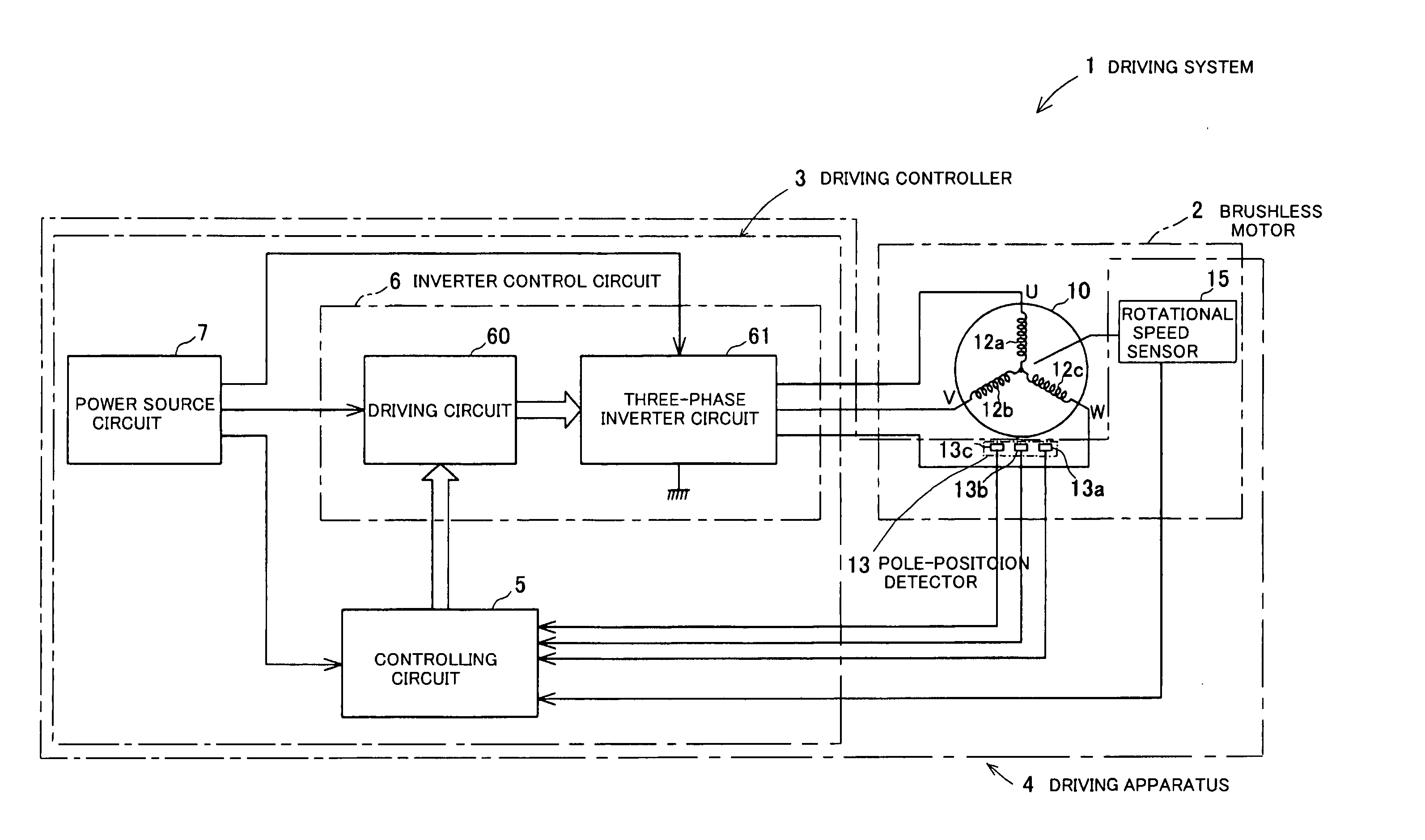
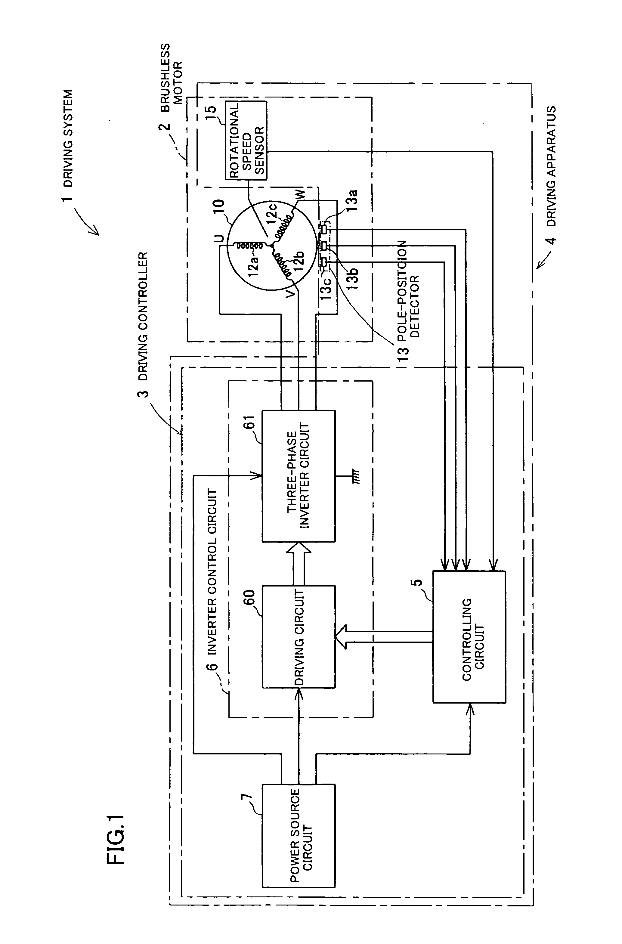
[0068] Referring to FIG. 1, a driving system 1 for driving a brushless motor relating to the embodiment consists essentially of a brushless motor 2 and a driving controller 3 for the motor. The driving controller 3 comprises a controlling circuit 5, an inverter control circuit 6 and a power source circuit 7. The brushless motor 2 comprises a motor body 10, a pole-position detector 13 and a rotational speed sensor (viz. a rotational speed sensing means) 15. Describing in detail, the driving system 1 includes a driving apparatus 4 involving the pole-position detector 13 and the rotational speed sensor 15 of the brushless motor 2 and the ...


PUM


Abstract

A driving system for driving a brushless motor effects a rotation control of a rotor by sequentially switching application of a current to magnetic coils disposed in a stator in response to a detection signal from a pole-position detector. The driving system comprises a controlling circuit for generating a driving signal, an inverter control circuit for controlling application of the current to the coils by adjusting opening and closing of switching devices in response to the driving signal, and a rotational speed sensor. The controlling circuit generates a braking signal when a rotational speed of the rotor is beyond a predetermined value, and transmits the braking signal to the inverter control circuit. The inverter control circuit effects a braking control in response to the braking signal by application of the current to at least one coil except those coils being excited upon reception of the braking signal.

Description

BACKGROUND OF THE INVENTION [0001] 1. Field of the Invention [0002] The present invention relates to an improvement of a driving apparatus for driving a brushless motor, and more particularly to the driving apparatus for driving the brushless motor that provides a stable rotational speed by a smooth braking. [0003] 2. Description of the Related Art [0004] Recently, a brushless motor is becoming increasingly common in place of a DC motor with a brush. The brushless motor comprises a commutation system that electromagnetically detects a rotation of a rotor and switches application of a current to magnetic coils, instead of a mechanical commutation system that comprises a mechanical brush and a commutator. Thus, the brushless motor, compared with the motor provided with the mechanical commutation system, has advantages of a reduction of a noise resulting from the rotation and a high durability. [0005] The brushless motor is employed as a driving source for various kinds of apparatus su...

Claims


Application Information

Patent Timeline
IPC IPC(8): H02P6/06H02P6/08H02P6/24
CPCH02P6/24H02P6/165H02P6/17
Inventor TACHIBANA, TOSHIYUKI
Owner ITO DENKI KK
Why Eureka
Try Eureka