Method and apparatus for channel equalization

Inactive Publication Date: 2005-02-03
MARVELL ASIA PTE LTD
View PDF44 Cites 25 Cited by
  • Summary
  • Abstract
  • Description
  • Claims
  • Application Information

AI Technical Summary

Benefits of technology

A method for equalizing a signal is also disclosed that comprises receiving a signal transmitted through a communication channel and performing a first equalization process on the signal utilizing a first equalizer having maximum phase coefficient values. Thereafter, performing a second equalization process on the signal utilizing a second equalizer having second equalizer coefficient values wherein the first equalization process and the second equalization process reduce the distorting effects of transmission through the channel.

Problems solved by technology

For example, audio and video content is generally bandwidth intensive.
Often networks are being burdened with more users and larger and more complex software applications.
These applications are bandwidth intensive and the complex software applications create larger files.
Although many networks are currently at bandwidth capacity additional demands are continually being placed on these networks.
While different communication standards (SONET, ATM) and different communication mediums (fiber optic cable, coaxial cable) may make it possible to increase data rates, the cost associated with migration is extremely prohibitive.
The cost associated with cable installation as well as the retraining of service personnel alone is tremendous.
Although widely deployed and inexpensive to manufacture, twisted pair copper is bandwidth limited.
As a result, data signals transmitted at very high rates in the gigabit per second range over the twisted pair copper, or other medium, are subject to significant levels of distortion.
Upon reception, recovering the transmitted signal may be impossible due to this distortion.
While it is possible to perform signal processing on the distorted signal, or even perform processing on the signal prior to transmission to counter the effects of the distortion, such prior art attempts have been insufficient to achieve very high data transmission rates with acceptable error rates.
While the DFE with slicer feedback is capable of decreasing the error rate under certain conditions, it suffers from catastrophic failure when presented with a string of slicer errors as feedback to the DFE.
Catastrophic failure is even more likely when error correction is adopted.
This is not an acceptable solution and generally will not fall within the specifications set forth by most communication standards.

Method used


Image

  • Method and apparatus for channel equalization
  • Method and apparatus for channel equalization
  • Method and apparatus for channel equalization

Examples


Embodiment Construction

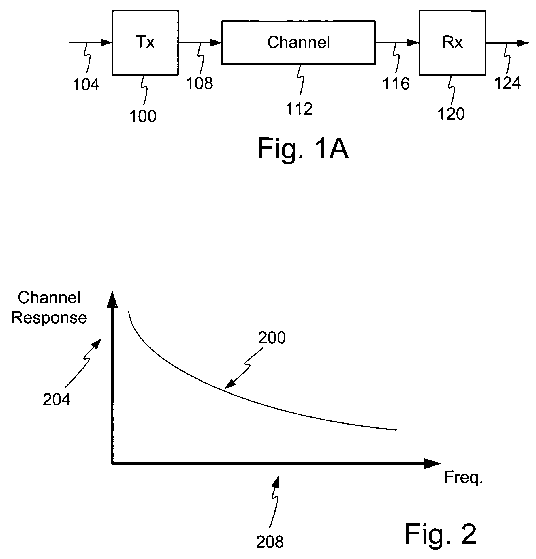
FIG. 1A illustrates an example embodiment of a transmitter and a receiver. As shown, a transmitter 100 includes a transmitter input 104 and a transmitter output 108. The output 108 of the transmitter 100 connects to a channel 112. The channel 112 connects to an input 116 of a receiver 120. The receiver 120 includes a receiver output 124. The receiver output 124 may connect to a computing device, terminal, switch, router, network processing device, or any device configured to receive data over the channel 112.

The transmitter 100 may comprise any device configured to transmit data from a first location to a second location. Likewise, the receiver 120 may comprise any device configured to receive data transmitted from the first location to the second location. It is contemplated that a transmitter 100 and receiver 120 may be located at both ends of the channel 112 to enable transmission in both directions. In one embodiment the transmitter 100 and receiver 120 are located in a network...


PUM


Abstract

A method and apparatus is disclosed to overcome the effects of intersymbol interference during data transmission. Overcoming the effects of intersymbol interference makes possible higher data transmission rates for a given error rate. In one embodiment a receiver processing system a first, second and third filter, such that the second and third filter comprise feedback filters. Filter coefficients are calculated to reduce the undesirable effects of the channel, such as intersymbol interference. A training process occurs to establish the first filter as a mixed phase filter and the third filter as minimum phase filter. The second filter is configured based on the transfer function of the channel and one or more coefficients may be set to a predetermined value.

Description

FIELD OF THE INVENTION The invention relates to communication systems and in particular to a method and apparatus for channel equalization. RELATED ART Demand for high rate data transmission continues to increase in response to new service offerings and expanded communication network usage, such as for home and business tasks. For example, audio and video content is generally bandwidth intensive. In addition, many tasks are now commonly handled via a computer network, such as over the Internet, including ordering business supplies, exchanging documents, or information gathering. Moreover, bandwidth demand placed upon a companies local area network is increasing. Often networks are being burdened with more users and larger and more complex software applications. These applications are bandwidth intensive and the complex software applications create larger files. Although many networks are currently at bandwidth capacity additional demands are continually being placed on these netwo...

Claims


Application Information

Patent Timeline
IPC IPC(8): H04L25/03H04B3/06
CPCH04L25/03343H04L25/03146
Inventor JONES, WILLIAM W.ZIMMERMAN, GEORGE A.
Owner MARVELL ASIA PTE LTD
Why Eureka
Try Eureka