Process for obtaining a flexible/adaptive thermal barrier

Active Publication Date: 2005-02-03
SN DETUDE & DE CONSTR DE MOTEURS DAVIATION S N E C M A
View PDF2 Cites 8 Cited by
  • Summary
  • Abstract
  • Description
  • Claims
  • Application Information

AI Technical Summary

Benefits of technology

It will be understood that since the power of the torch is set to a high value and the ceramic layer is produced in a single pass, the new drops of molten material arrive on material that is still very hot, thereby causing excellent bonding by welding between the ceramic grains in the vertical direction. This is favored by choosing the speed of movement of the torch to be as low as possible, preferably between 2 mm/s and 10 mm/s. Thus, the temperature at the point of deposition is high, thereby making it possible to obtain a dense microstructure with few horizontal microcracks, delaminations and pores, and better cohesion of the material. Spraying in a single pass is a key parameter that has a direct impact on the s

Problems solved by technology

A horizontal crack can then be initiated between two layers, this being prejudicial to the integrity of thermal barrier.
Moreover, since the ceramic layer thus formed beneath the jet is very hot, when the jet is moved the cooling of the layer upon contact with the ambient air causes a large vertical thermal gradient, this

Method used


Image

  • Process for obtaining a flexible/adaptive thermal barrier
  • Process for obtaining a flexible/adaptive thermal barrier
  • Process for obtaining a flexible/adaptive thermal barrier

Examples


Example

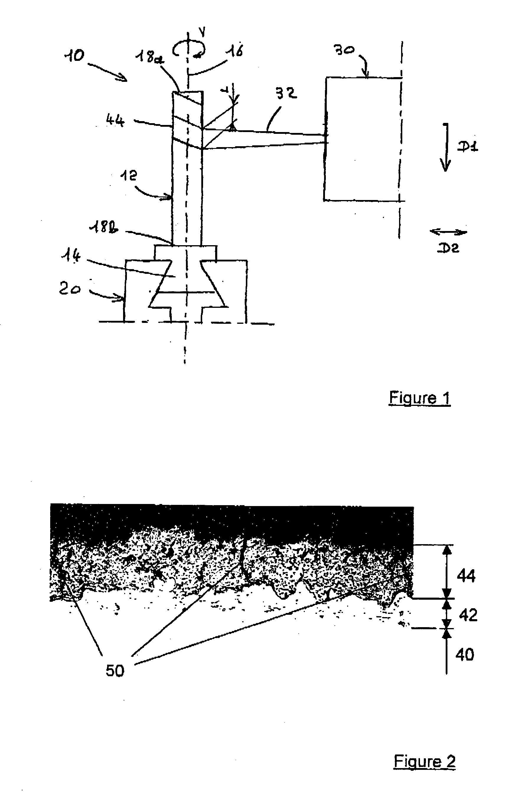
Reference will firstly be made to FIG. 1.

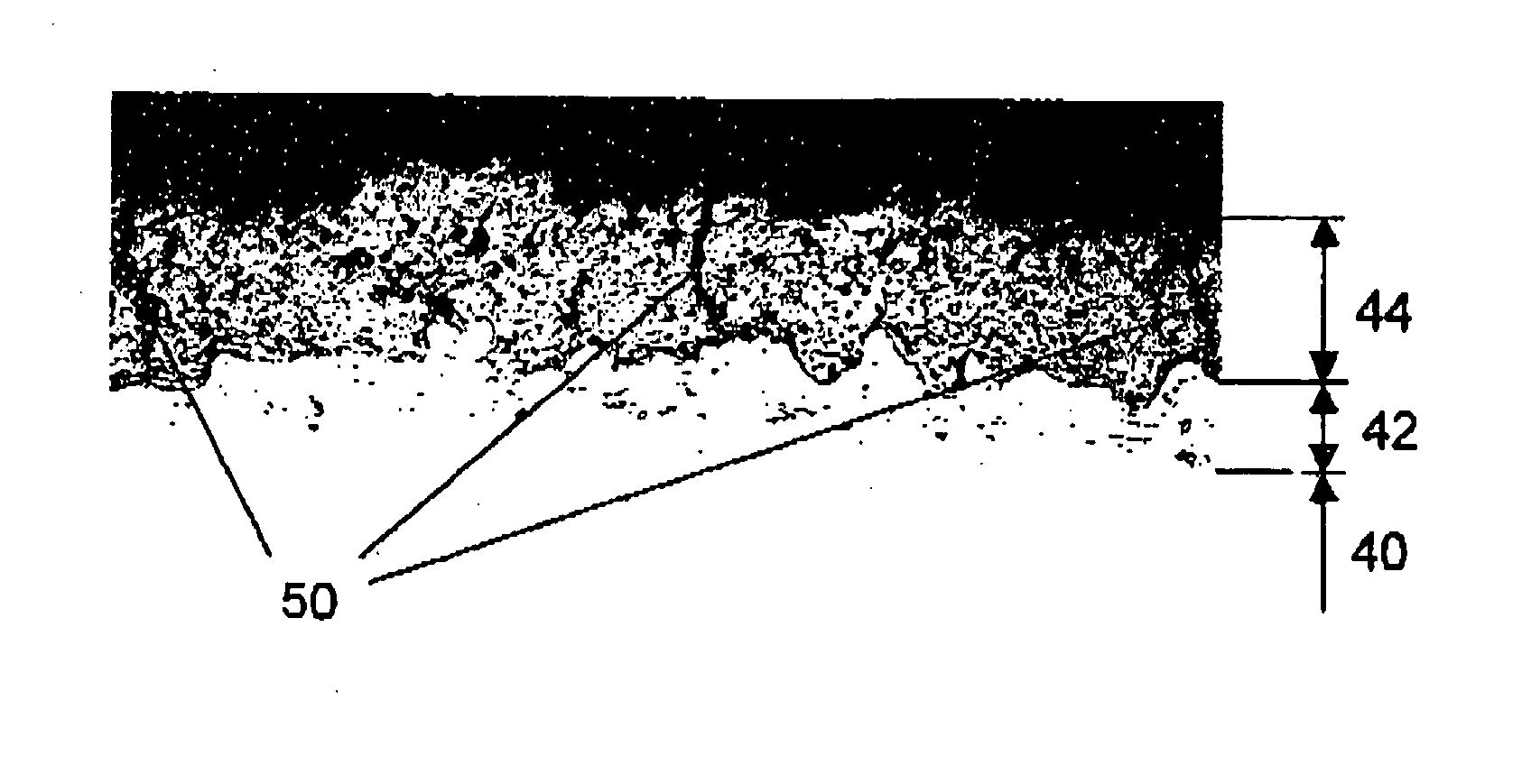
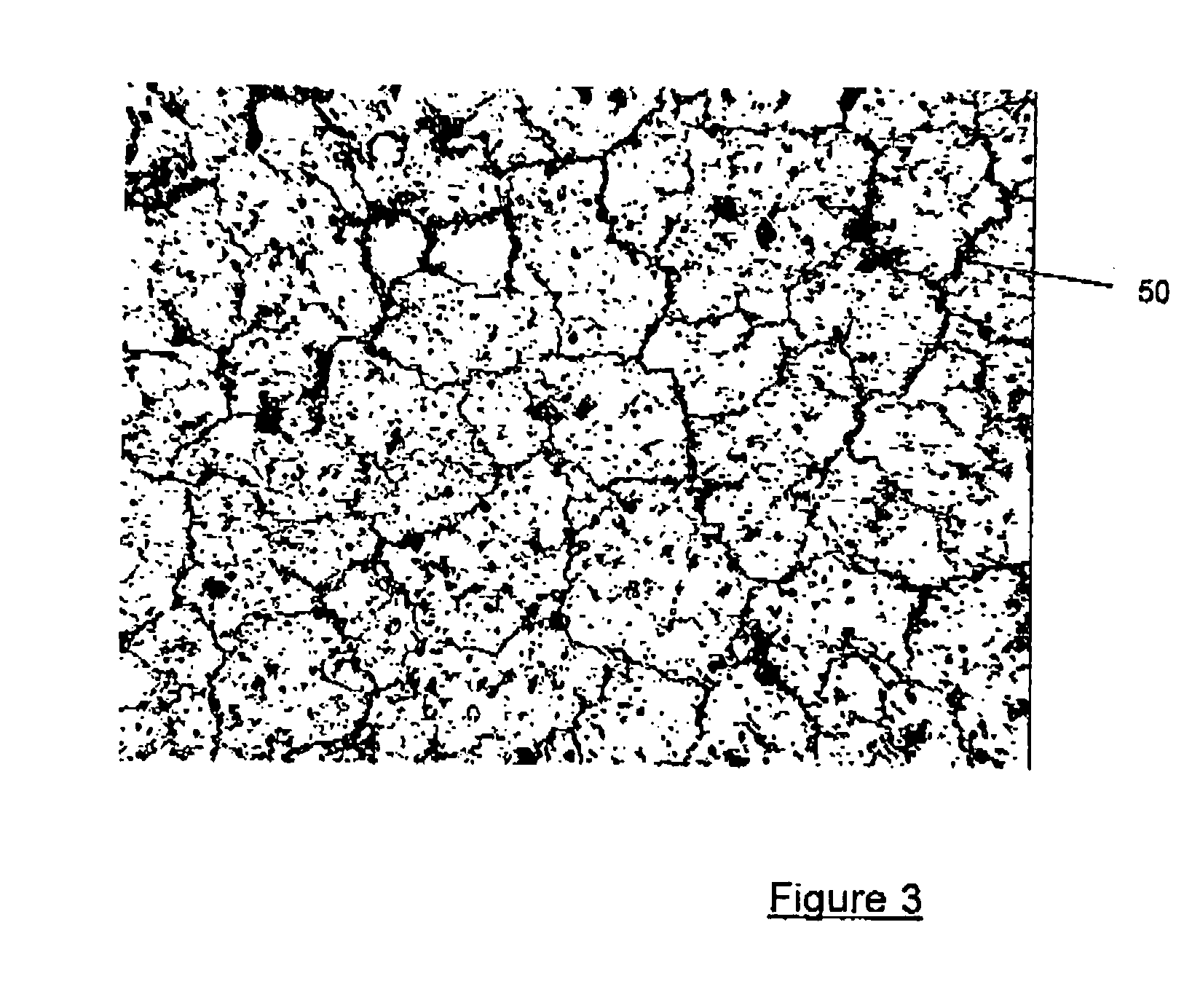
The component to be coated with a thermal barrier is a turbine blade 10 made of a nickel-based superalloy with directional solidification. The thermal barrier comprises an MCrAlY sublayer covered with a 125 μm ceramic layer made of zirconia ZrO2 with 8% yttria Y2O3.

The airfoil 12 of the blade 10 is covered with an MCrAlY sublayer deposited using the standard processes.

The blade 10 is then held by its root 14 on a rotary assembly 20 capable of making the blade rotate about its axis 16, that is to say about itself, in the length direction, the airfoil 12 being presented in front of a plasma torch 30, the jet of which is denoted by 32. The plasma torch 32 here is the F4 model sold by the company whose registered name is Sultzer Metco.

The torch is placed at 50 mm from the blade 10, the blade 10 then being rotated about its axis 16. The torch 30 is turned on and the jet 32 firstly touches the tip 18a of the blade 10 and moves progressivel...


PUM

PropertyMeasurementUnit
Thicknessaaaaaaaaaa
Massaaaaaaaaaa
Massaaaaaaaaaa

Abstract

The invention proposes a process for obtaining a flexible/adaptive thermal barrier, the thermal barrier comprising a ceramic layer (44) deposited on a substrate (40) covered with a sublayer (42), the ceramic layer (44) being deposited by thermal spraying using a torch (30). Such a process is noteworthy in that:
    • a. the ceramic layer (44) is deposited in a single pass; and
    • b. the torch (30) is set to give the ceramic layer (44) a thickness of at least 80 μm.

Description

TECHNICAL FIELD OF THE INVENTION The invention relates to flexible / adaptive thermal barriers, that is to say to thermal barriers having sufficient flexibility to adapt to the deformations of the substrate, whether they be of mechanical origin or of dilatometric origin owing to a thermal gradient. The invention relates more particularly to an economic process for obtaining such barriers by thermal spraying. STATE OF THE ART AND PROBLEM POSED At the present time, turbomachine components exposed to the hot combustion gas flux are made of superalloys resistant to high temperatures and protected from heat and corrosion by a coating called a thermal barrier. Presently, a thermal barrier usually consists of: an aluminous sublayer of NiPtAl or MCrAlY (where M=Fe, Ni, Co or NiCo) forming a chemical obstacle to oxidation and to corrosion; a thermally insulating ZrO2-YO ceramic layer. In what follows and for convenience of language, the term “vertical” will be used for the direction appro...

Claims


Application Information

Patent Timeline
IPC IPC(8): C23C4/02C23C4/12C23C4/18
CPCC23C4/02C23C4/18C23C4/127C23C4/134
Inventor BENGTSSON, PERDUDON, LAURENT
Owner SN DETUDE & DE CONSTR DE MOTEURS DAVIATION S N E C M A
Why Eureka
Try Eureka