Method for processing stack gas emissions

a technology of stack gas and processing method, which is applied in the direction of sustainable manufacturing/processing, separation processes, and final product manufacturing, etc., can solve the problem that the solution may require considerable capital investment in facilities

Inactive Publication Date: 2005-02-03
SOLAR REACTOR TECH
View PDF36 Cites 54 Cited by
  • Summary
  • Abstract
  • Description
  • Claims
  • Application Information

AI Technical Summary

Problems solved by technology

That solution may require considerable capital...

Method used


Image

  • Method for processing stack gas emissions
  • Method for processing stack gas emissions
  • Method for processing stack gas emissions

Examples


Embodiment Construction

Embodiments of the present invention can be used in conjunction with one or more fossil fueled electric power generating plants. Where, in the text and drawings, a ‘utility plant’ is mentioned, that mention is meant to encompass both an arrangement concerned with one fossil fueled electric power generating plant, and an arrangement in which a plurality of such plants are involved.

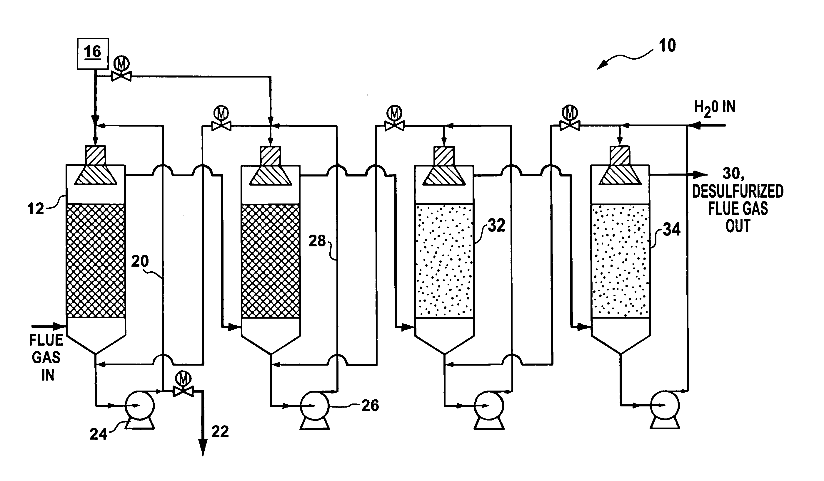
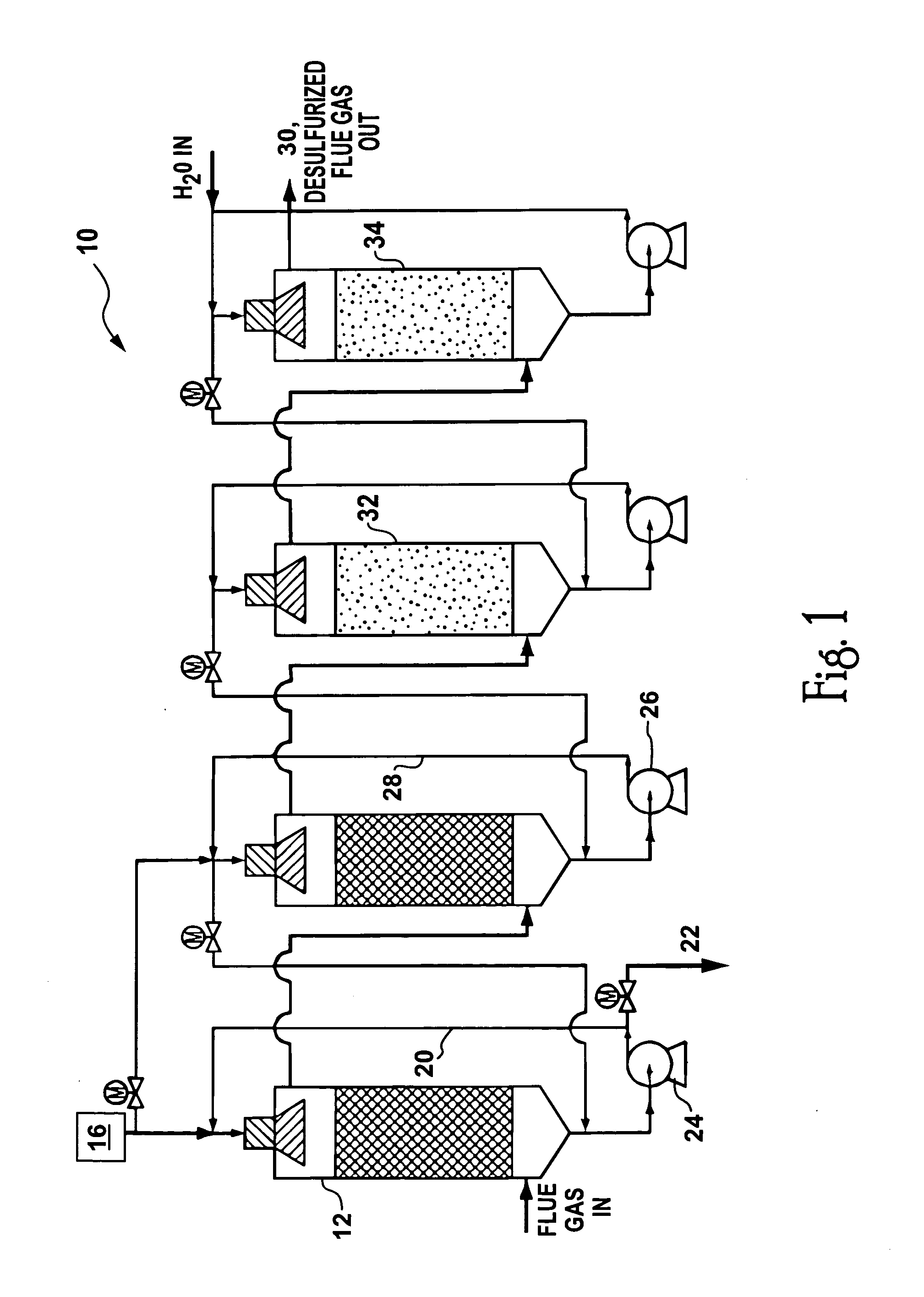
In a stack gas cleaning process, dirty stack gas from the fossil fueled utility plant, previously cooled by heat exchangers or other structures to approximately 100° C., is directed to the first stage of a multiple stage reactor / gas washing apparatus as shown generally at 10 in FIG. 1. Each stage consists of apparatus for introducing the stack gas stream, later venting the stream, and passing it through a reaction volume. For example, the reaction volume may be a column of glass helices, several raschig rings, or other shapes constructed of glass, ceramic or otherwise appropriate material, designed to fu...


PUM


Abstract

Apparatus and methods for augmenting the Mark 13a process of Van Zelzen et al., by providing for the addition of dispatchable energy storage and/or additional waste stream treatments. Sulfur-containing stack gas emissions from the burning of fossil fuels for electricity production are cleaned, removing the sulfur by use of the Bunsen reaction. The process produces hydrogen and sulfuric acid as byproducts. The hydrogen output of the process can be used to co-produce electricity in a reversible fuel cell, and optionally can be stored so that electricity can be produced during periods of high demand. Optionally the hydrogen can be reacted with air-nitrogen or nitrogen from the combustion gasses to produce ammonia. The sulfuric acid can optionally be reacted with iron or aluminum to produce iron or aluminum sulphates and additional electricity. In addition, mercury removal from the gas emissions from burning fossil fuels (primarily coal) can be performed.

Description

BACKGROUND OF THE INVENTION 1. Field of the Invention The present invention relates generally to methods and apparatus for treatment of fluids and more particularly for sulfur removal from fluids. 2. Description of Related Art In a typical fossil fuel utility plant, fossil fuel is burned using combustion air, and cooling water, to provide electric power, and, as byproducts, process heat and ‘dirty’ stack gas which typically includes CO2, SO2, NOX, H2O, N2 and O2. Many electric power generating plants are equipped to clean stack gases, and to recover at least some of the process heat. Where the market for electric power which could be served from the plant varies, e.g., by time of day or seasonally, it has become typical to design and operate the plant to produce some fraction below 100%, of the marketable power which is neither as small as the minimum load that the system depending on the plant ever experiences, nor as much large as the maximum load experienced, or, with project...

Claims


Application Information

Patent Timeline
IPC IPC(8): C01B7/00C01B17/00C25B1/02C25B1/24F02MH01M8/06H01M8/18H01M8/22
CPCB01D53/502C01B7/093C01B13/0203C01B13/0207C01B17/74Y02E60/50C25B1/24H01M8/0612H01M8/0656H01M8/22C25B1/02Y02P20/133Y02P70/50
Inventor HEATON, HARLEY L.PARKER, ROBIN Z.PARKER, MELAHN L.KELLER, JIMMY B.SALISBURY, BRUCE A.
Owner SOLAR REACTOR TECH
Why Eureka
Try Eureka