Microfluidics packages and methods of using same

Inactive Publication Date: 2005-02-03
AGENCY FOR SCI TECH & RES
View PDF11 Cites 52 Cited by
  • Summary
  • Abstract
  • Description
  • Claims
  • Application Information

AI Technical Summary

Benefits of technology

The microfluidics packages and methods of the present invention reduce or overcome many deficiencies of the prior art. In addition, specific embodiments may be made reusable. As used herein “reusable” means that fluid samples that are conside

Problems solved by technology

Currently the interface between the macroscopic (“real”) world and the microfluidics world is one of the major obstacles in the practical use of lab-on-a-chip components.
There are several problems associated with passing microfluidics samples from the “real” world to the microfluidics device, including sample contamination of associated instrumentation, the desire to decrease dead volume in such devices, and a desire to precisely control the volume of sample required.
In most respects it is undesirable that the blood, or any related biological product, can diffuse or otherwise contaminate the instrumentation (pumps, valves, tubes and the like).
If contamination occurs, the instrumentation must be cleaned before it can be used for a new sample.
It is clear that the whole package 1 will be contamin

Method used


Image

  • Microfluidics packages and methods of using same
  • Microfluidics packages and methods of using same
  • Microfluidics packages and methods of using same

Examples


Embodiment Construction

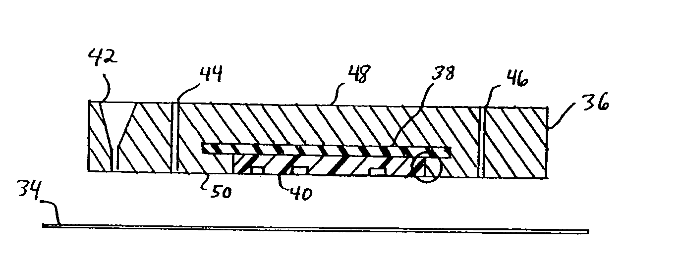
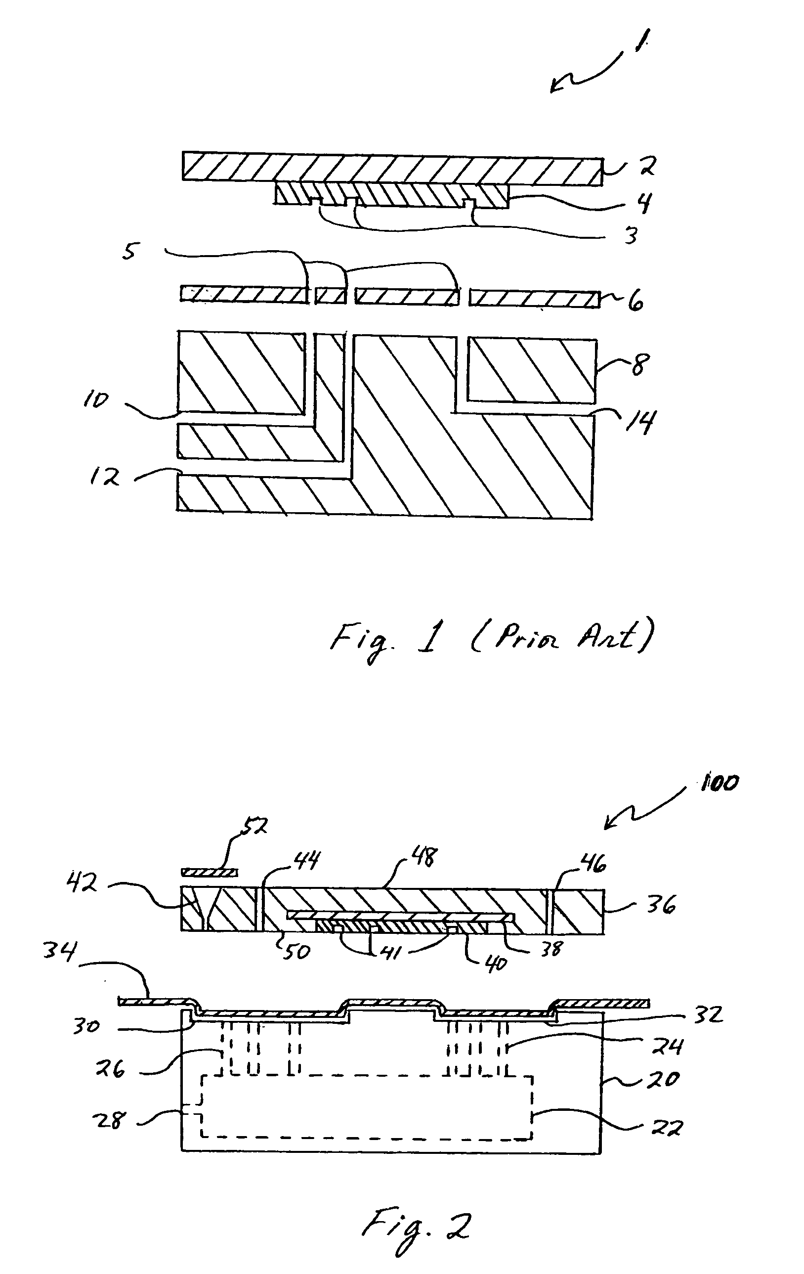
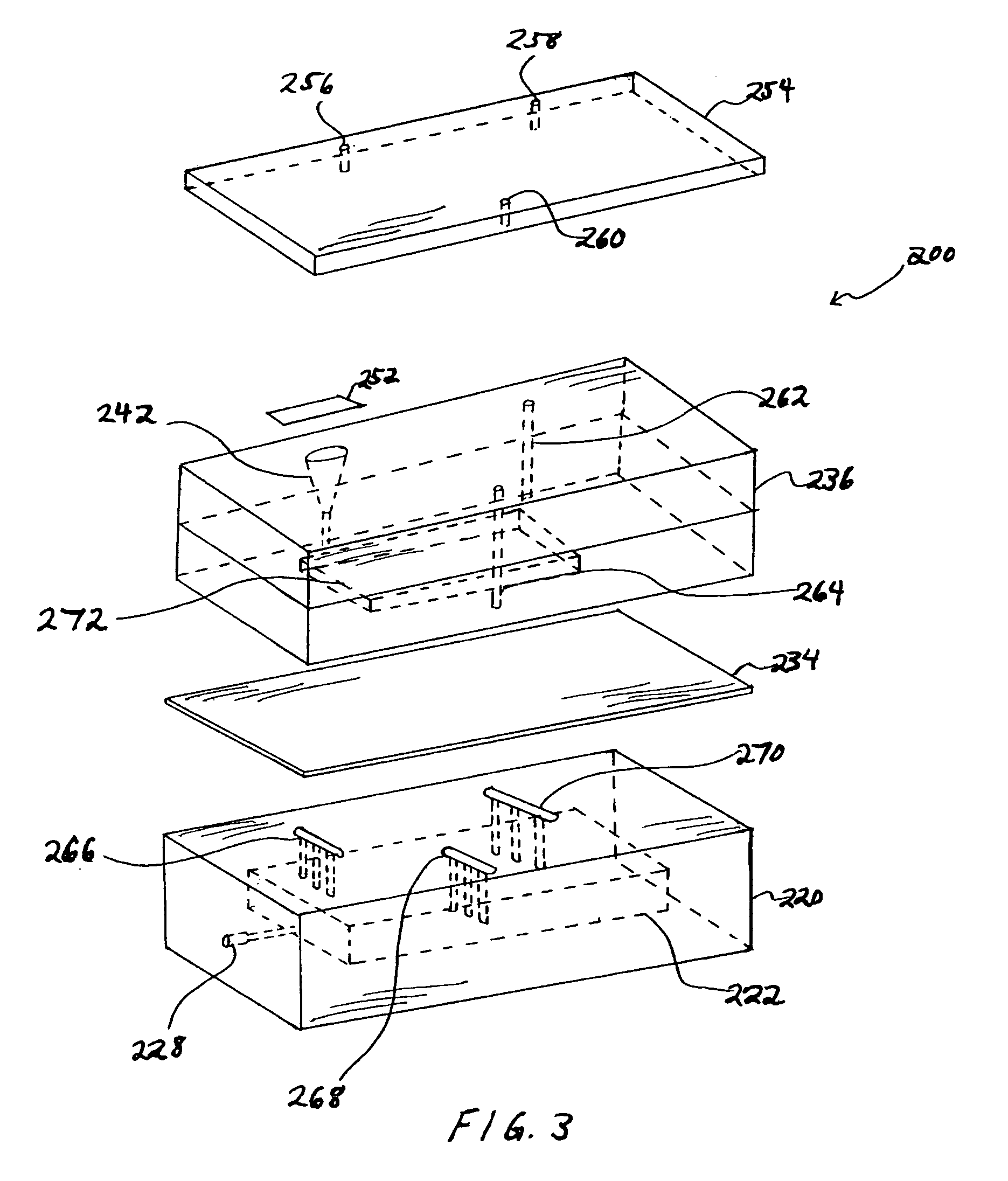
The microfluidics packages and methods of the present invention utilize a thin polymeric barrier film over a patterned part. As used herein the term “patterned” includes, but is not limited to, machined parts and parts having patterns created by other methods, for example printing, embossing etching, and the like.

In the context of a microfluidics packaging, the invention uses the concept of forming a polymeric barrier film. By retaining the polymeric barrier film against a patterned substrate with a vacuum, the fluid flow channels of the substrate are thus lined with a polymeric barrier film. All the “clean” reagents can be pumped into the chip through inlets on a cover plate. The reservoir on the card is employed to hold “dirty” reagents (for example, blood or other biological samples), which may contaminate the instrument, and to provide precise volume control. By injecting air or applying hydraulic pressure over the reservoir, the sample in the reservoir can be deployed into t...


PUM


Abstract

Microfluidics packages and methods of use are described, comprising in one embodiment a substrate having a top surface and means to lower pressure on the top surface; a fluidics card having a bottom surface and means to allow fluids to traverse through the card; and a polymeric barrier film, the polymeric barrier film positioned between the top surface of the substrate and the bottom surface of the fluidics card.

Description

BACKGROUND INFORMATION 1. Technical Field The invention is generally related to the field of micofluidics. More specifically, the invention relates to novel microfluidics packages and methods of using same which address problems of contamination of instrumentation, dead volume, and volume control in such devices. 2. Background Art Currently the interface between the macroscopic (“real”) world and the microfluidics world is one of the major obstacles in the practical use of lab-on-a-chip components. There are several problems associated with passing microfluidics samples from the “real” world to the microfluidics device, including sample contamination of associated instrumentation, the desire to decrease dead volume in such devices, and a desire to precisely control the volume of sample required. These problems can be understood by considering the example of handling a blood sample. In most respects it is undesirable that the blood, or any related biological product, can diffuse ...

Claims


Application Information

Patent Timeline
IPC IPC(8): B01L3/00
CPCB01L3/502707B01L7/52B01L2200/0689B01L2200/141Y10T436/2575B01L2300/0887B01L2300/123B01L2400/0655B01L2300/0816
Inventor SAMPER, VICTORCONG, LINJI, HONGMIAO
Owner AGENCY FOR SCI TECH & RES
Why Eureka
Try Eureka