
Symbolic analysis of electrical circuits for application in telecommunications

Inactive Publication Date: 2005-02-03
TELEFON AB LM ERICSSON (PUBL)
View PDF8 Cites 32 Cited by
  • Summary
  • Abstract
  • Description
  • Claims
  • Application Information

AI Technical Summary

Benefits of technology

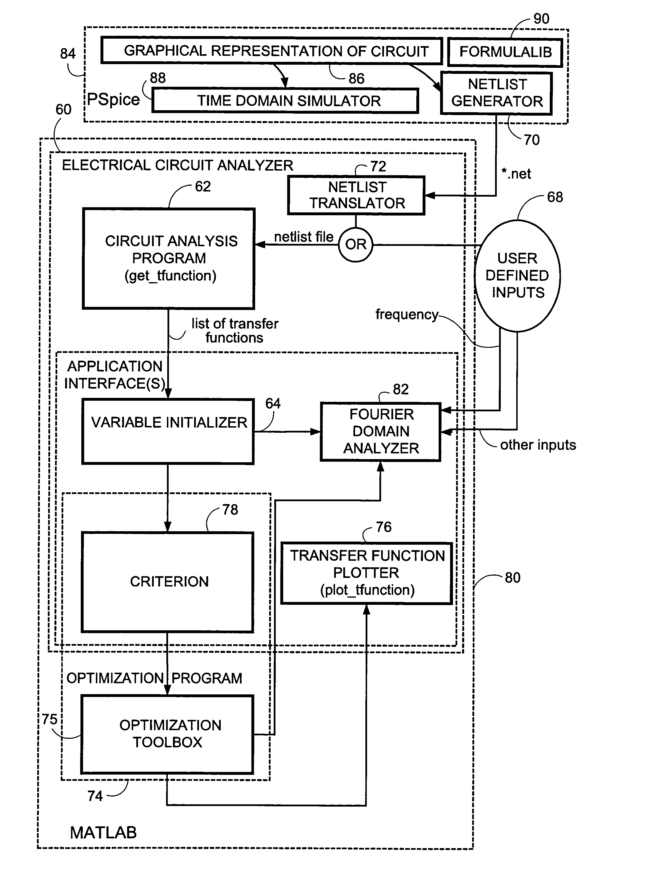
In general, matrix equations can become increasingly time-consuming and especially memory-consuming when dealing with very large circuits containing many components. Additionally, some components require extensive use of auxiliary equations, which may also contribute to memory deficiencies. In order to minimize these factors, as one of its aspects the electrical circuit analyzer implements a block matrix approach rooted in Krakovian algebra, which is related to matrix algebra. Then, using standard programs (such as, for instance, those implemented in Matlab), the Krakovian algorithm can be easily executed.
According to an advantage this block / subcircuit approach, the size of the entire admittance matrix comprising block Krakovians corresponding to the subcircuits can be recursively reduced, working only with those matrix blocks that are relevant for a specific application. Moreover, the resulting admittance matrix Y dynamically changes its dimensions depending on the number of equations required to describe a subcircuit. Therefore, the solution matrix has approximately the same dimension as the number of relevant equations.

Problems solved by technology

Analyzing electrical circuits in the telecommunications industry has special considerations and requirements which are not fully satisfied by existing analysis products.
But whereas some existing analysis products are particularly applicable for non-linear devices, in telecommunications circuits the non-linearity of certain devices (such as line drivers, for example) is generally quite small and of negligible influence on the overall telecommunications system.
In telecommunications systems, other factors such as the value spread of components incorporated in the circuitry of the system is of significantly greater importance and can cause severe problems (e.g., for high-speed data transceivers).
Moreover, existing circuit analysis products such as Analog Insydes do not provide support for some devices which are often employed in telecommunications environments, such as cables / communication channels, non-ideal transformers with several windings, digital filters, etc.
For example, transformers with more than two windings are very difficult to model and analyze.
Thus, non-support for such telecommunications devices drastically curtails employment of the existing circuit analysis products in the telecommunications environment.
These simulators lack full suitability for analysis of telecommunication circuits.

Method used


Image

  • Symbolic analysis of electrical circuits for application in telecommunications
  • Symbolic analysis of electrical circuits for application in telecommunications
  • Symbolic analysis of electrical circuits for application in telecommunications

Examples


Embodiment Construction

In the following description, for purposes of explanation and not limitation, specific details are set forth such as particular architectures, interfaces, techniques, etc. in order to provide a thorough understanding of the present invention. However, it will be apparent to those skilled in the art that the present invention may be practiced in other embodiments that depart from these specific details. In other instances, detailed descriptions of well-known devices, circuits, and methods are omitted so as not to obscure the description of the present invention with unnecessary detail. Moreover, individual function blocks are shown in some of the figures.

1.0 Circuit Analysis Workstation

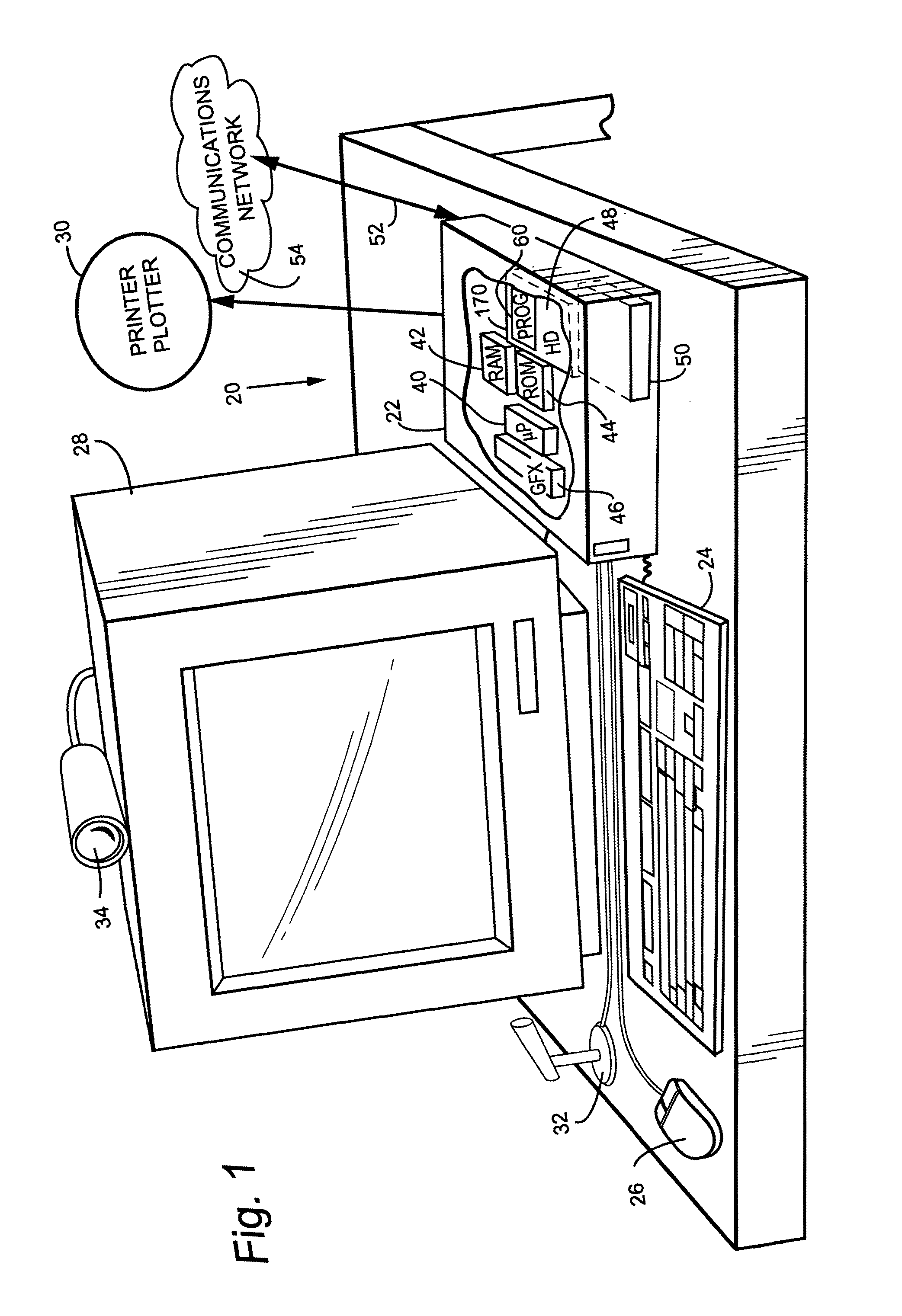
FIG. 1 shows an example embodiment of an circuit analysis workstation 20 which includes a general purpose computer 22 and various input / output devices such as keyboard 24, mouse pointing device 26, display 28, printer / plotter 30, microphone 32, and camera 34. Computer 22 may be, for example, a conv...


PUM


Abstract

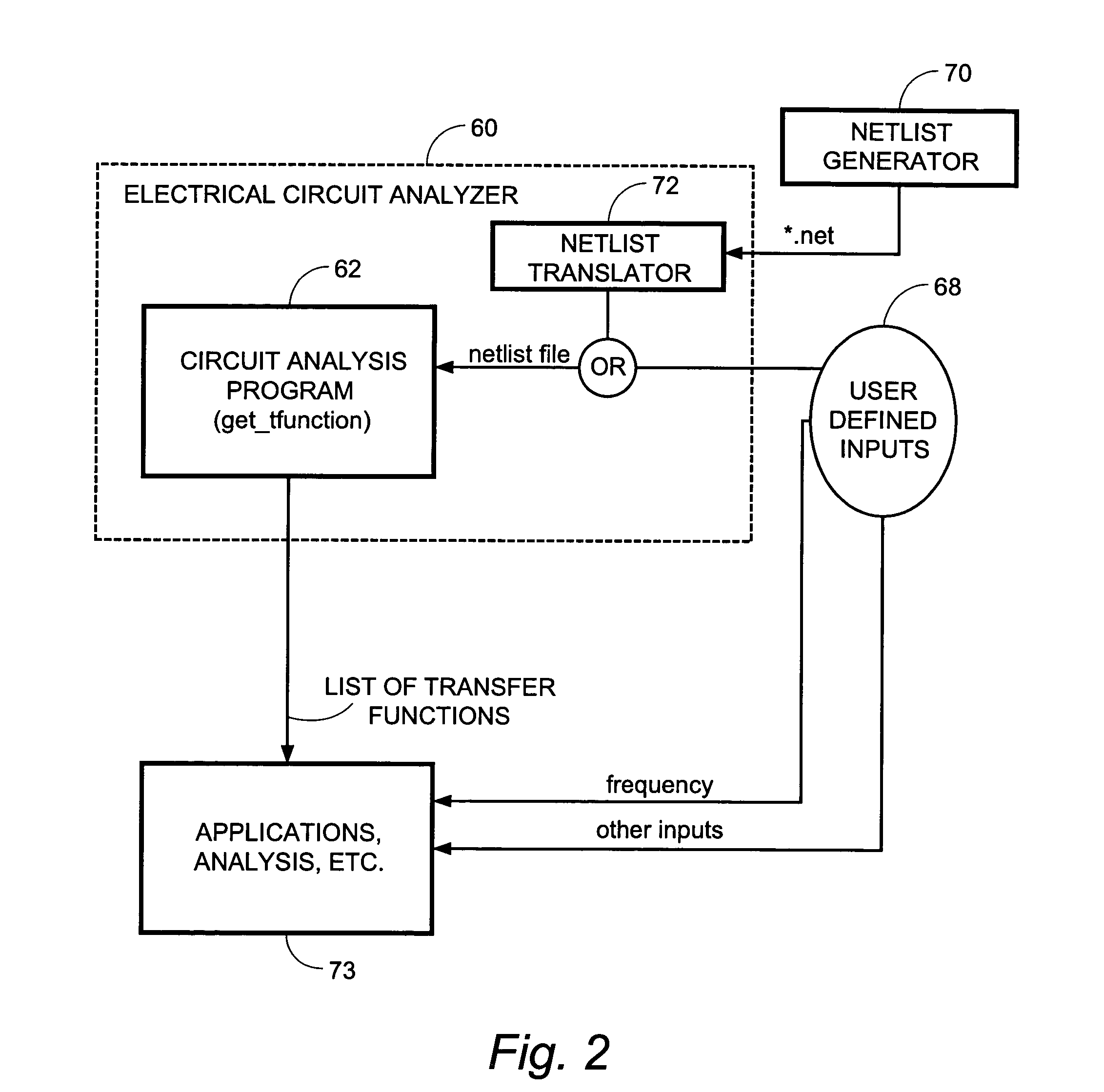
Analysis of an electrical circuit is performed using a computer program product (60) and a method. In accordance with the program and the method, a electrical circuit analyzer generates an admittance matrix for an electrical circuit which is being analyzed. The admittance matrix includes symbolic expressions rather than numerical expressions for at least some components of the electrical circuit. The electrical circuit analyzer linearly and algebraically solves an equation system including the admittance matrix for analyzing at least a part of the electrical circuit. The electrical circuit analyzer uses symbolic computation to solve the equation system including the admittance matrix for analyzing at least a part of the electrical circuit. The equation system including the admittance matrix can be solved in various types of analyses, including (1) determining a transfer function between specified nodes of the electrical circuit; and (2) optimizing a component of the electrical circuit. The electrical circuit analyzer sets up the admittance matrix Y by following a set of “rules”. Special rules are provided for certain telecommunications components, such as multi-winded transformers, loading coils, line-drivers, analogue cables, and filters. Inclusion of these special rules for telecommunications components enables the electrical circuit analyzer to be more applicable to telecommunications circuits than conventional analyzers. In accordance with a block / subcircuit matrix approach, an overall circuit is divided into plural subcircuits. In such case, the admittance matrix can comprise separate admittance blocks for each of plural subcircuits. Connectivity blocks which represent connectivity between the plural subcircuits are situated on a cross diagonal of the admittance matrix. The admittance matrix can then be conveniently utilized for analyzing at least a part of the electrical circuit. Advantages of this approach include recursively reducing the size of the matrices including the admittance matrix as subcircuits are added to the admittance matrix.

Description

BACKGROUND 1. Field of the Invention This invention relates to method and apparatus for the analysis of electrical circuits, and particularly to the analysis of circuits utilized in a telecommunications system. 2. Related Art and Other Considerations In various fields of technical endeavor it is often important to determine a transfer function between two arbitrary points of an electrical circuit or to analyze an electrical circuit for purposes such as, for example, optimizing component values. To this end various software products purport to model and analyze analogue electronic circuits. Some of these circuit analysis products make use of a general method, known as modified nodal analysis, for constructing and solving the circuit equations. Raymond A. DeCarlo and Pen-Min Lin, “Linear Circuit Analysis”, Oxford University Press, 2001, ISBN 0-19-51366-7. Nodal Analysis is based on Kirchoff's Current Law (KCL), i.e., the sum of all currents entering and leaving a node is zero. Ea...

Claims


Application Information

Patent Timeline
IPC IPC(8): G06F17/50H03F1/26
CPCG06F17/5036G06F30/367
Inventor FERTNER, ANTONILUPPERT, EDWIN
Owner TELEFON AB LM ERICSSON (PUBL)
Learn More