Storage tank for cryogenic liquids

a storage tank and liquid fuel technology, applied in the direction of liquid handling, packaging goods type, container discharging methods, etc., can solve the problems of difficult to store gaseous fuels as efficiently as liquid fuels, cryogenic storage presents its own challenges, and the volume is reduced. , the effect of reducing the volum

Inactive Publication Date: 2005-02-10
WESTPORT FUEL SYST CANADA INC
View PDF11 Cites 18 Cited by
  • Summary
  • Abstract
  • Description
  • Claims
  • Application Information

AI Technical Summary

Benefits of technology

The present invention provides for an ullage space that is at least partially evacuated upon completion of filling a cryogen vessel thereby reducing the volume necessary for the ullage space than otherwise required. Also, by reducing ullage space, this space can be evacuated during filling or prior to filling more quickly.
The present invention provides for an ullage space that is at least partially evacuated during refueling thus allowing for a consistent ullage volume regardless of the presence of any residual LNG in the ullage vessel prior to refueling.

Problems solved by technology

Substituting diesel with such gaseous fuels generally results in cost, availability and emissions benefits over diesel.
One challenge in using gaseous fuels for such applications, however, is that it is difficult to store gaseous fuels as efficiently as liquid fuels.
While, as mentioned above, there are special economies to utilizing LNG, cryogenic storage presents its own challenges.
One of the challenges of LNG is that, in many applications, once delivered into a holding tank, it needs extra space in which to expand if the LNG warms.
Excessive heat leakage into a cryogenic tank, as well as causing the LNG itself to expand, will cause the cryogenic liquid to boil.
Eventually, with continued heat leakage, LNG will boil or evaporate resulting in excessive stresses on the storage tank caused by pressure build-up.
However, for a variety of reasons, it is undesirable to routinely vent natural gas into the atmosphere.
Also, venting fuel is uneconomical as this releases unused fuel into the atmosphere.
For example incomplete evacuation of the space disposed between the outer jacket and inner vessel may cause heat leakage.
In any event, the inner vessel cannot be completely insulated.
One problem with this solution is that it is difficult to leave an adequate space during filling.
Visual fill lines may not provide the level of accuracy required.
Also, given the double vessel structure of many tanks, it is not easy to provide a sight port through to the inner vessel.
This introduces into the storage tank a mechanical failure point that is subjected to wear during and between each fill.
The introduction of such a failure point may, in many cases, be the failure point that determines the life of the tank.
Access to the interior of the tank, and therefore, to mechanical parts within the tank is difficult if not impossible due to the need to thermally isolate the inner tank from the outside environment.
Therefore, repair of a mechanical part is not practical in many cases.
As such, failure of a mechanical stop mechanism generally requires replacement of the storage tank.
Further, this method of providing an ullage space presents problems in the case where the cryogen tank has not been emptied between fills.
Also, gravity will frequently force, over time, LNG into the ullage vessel through the restrictive opening.
As such, the ullage space may not inadequately allow for LNG expansion upon completion of refueling.

Method used


Image

  • Storage tank for cryogenic liquids
  • Storage tank for cryogenic liquids
  • Storage tank for cryogenic liquids

Examples


Embodiment Construction

)

In the present method, a cryogenic tank is disclosed that utilizes pressure to provide an ullage space within an LNG tank at the completion of refueling the tank. Specifically, the Bernoulli principle is utilized to secure and maintain an at least partially evacuated ullage space within the LNG tank.

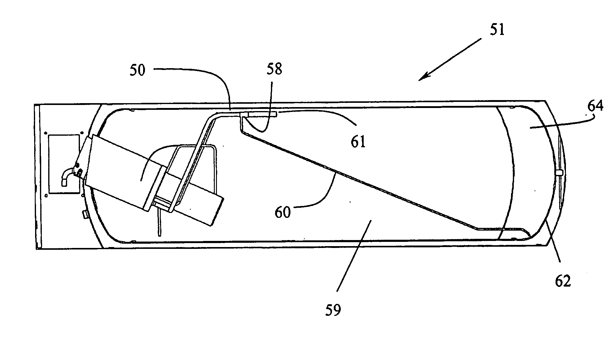
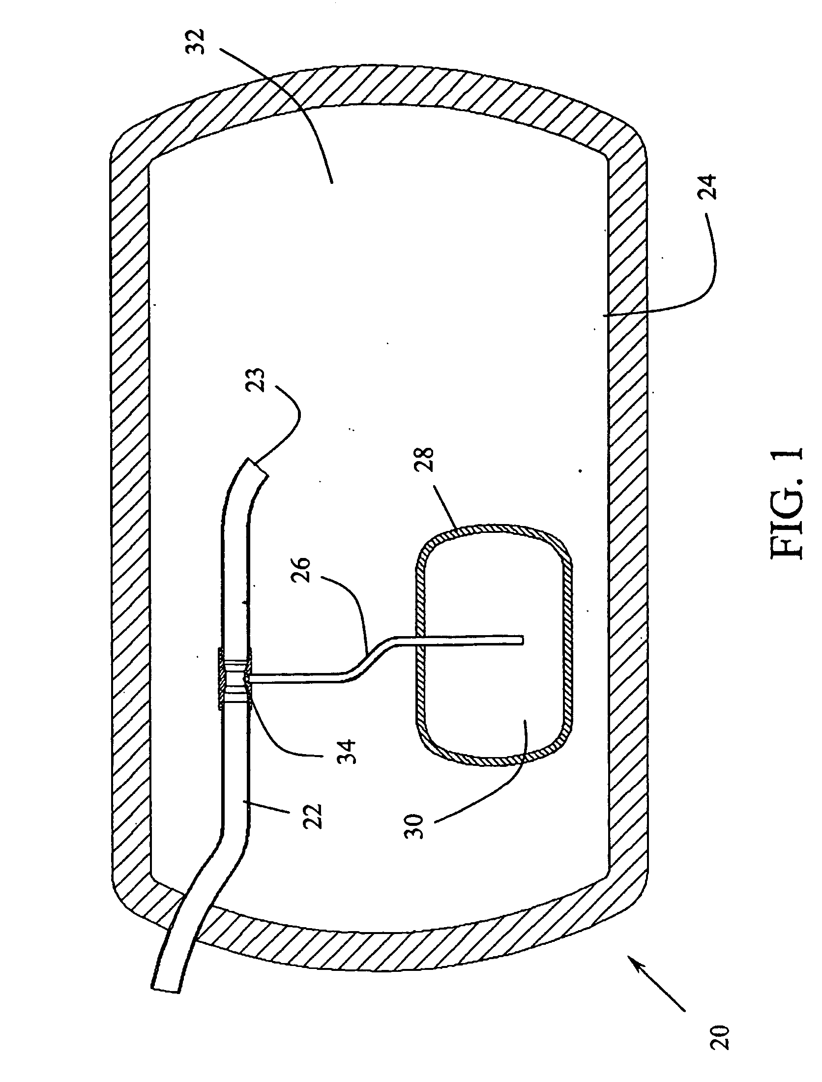
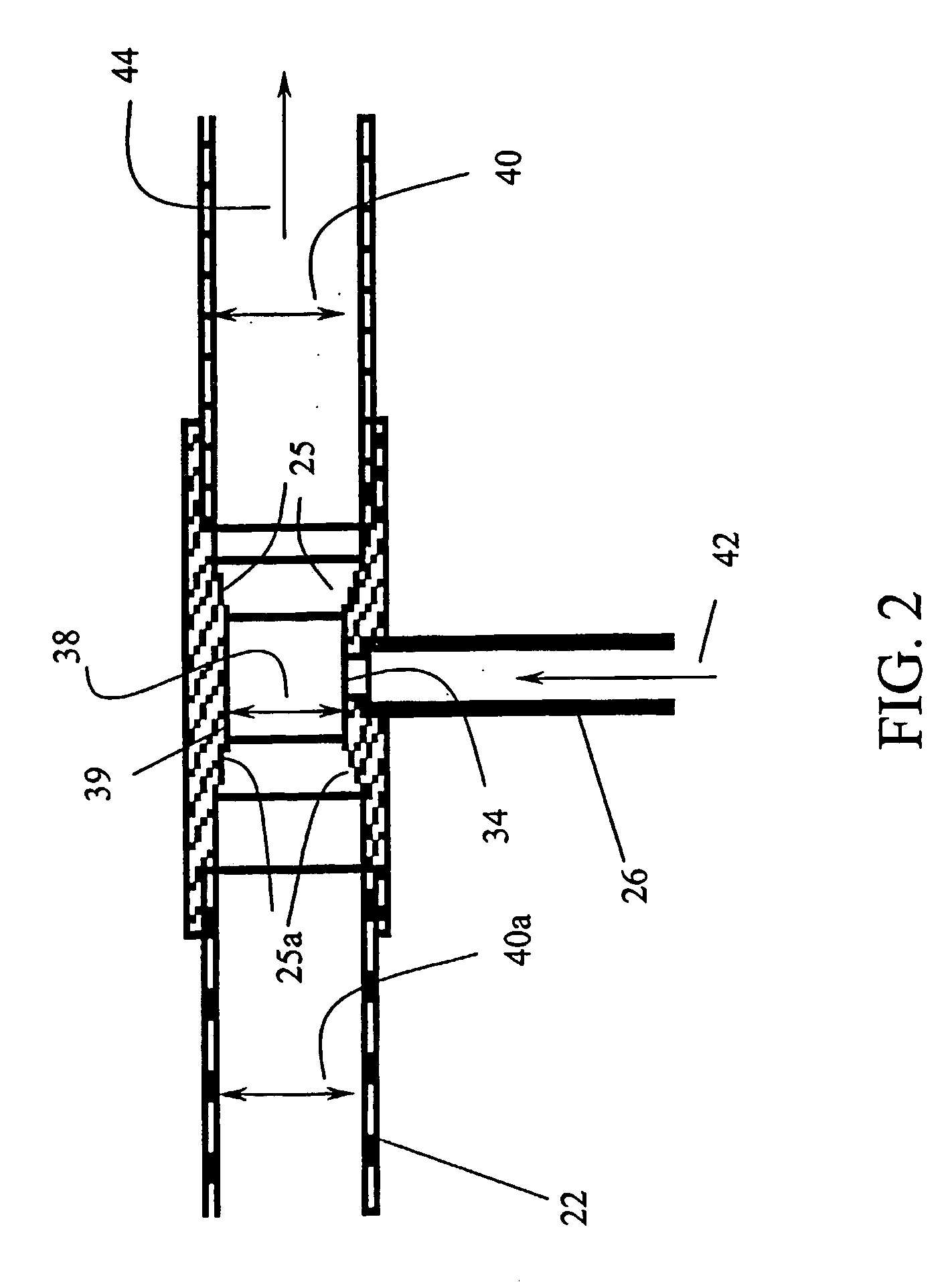
Referring to FIG. 1, cryogenic tank 20 is shown. Referring to FIG. 2, a close-up of cryogenic tank from FIG. 1 is shown near junction 34. Refueling line 22 extends from a point outside tank 20 to opening 23 disposed within inner vessel 24. Refueling line 22 has at least two distinct cross-sectional areas along its path. These areas are determined by venturi diameter 38 and line diameter 40 as the refueling line is generally cylindrical. Slope 25 joins that portion of refueling line 22 with venturi diameter 38 with the portion of refueling line 22 with line diameter 40. Venturi diameter 38 is smaller than line diameter 40. Slope 25 is set at an angle joining the venturi diameter secti...


PUM


Abstract

The storage tank for cryogenic liquids incorporates an ullage vessel that provides for an ullage space. The ullage vessel is in communication through an ullage line to a fill line that provides cryogen to a cryogen space. The junction where the ullage line and fill line meet is of a certain cross-sectional area. Downstream of the junction within the fill line, measured in reference to the direction of cryogen flow during a coruse of filling the cryogen space, is of a greater cross-sectional area than is the case at the junction. This creates a pressure reduction at the junction during a course of filling that causes a net flow of material from the ullage space over the course of filling. Once the cryogen tank is liquid full causing cryogen to be redirected down the ullage line, the smaller cross-sectional area of the ullage line compared to the fill line causes a reduction in flow of cryogen which is detected by the fill pump causing filling to stop providing the ullage space. A means of draining the ullage vessel prior to and during filling of the storage tank is provided.

Description

FIELD OF THE INVENTION The present invention relates to a storage tank design that incorporates an ullage space. BACKGROUND OF THE INVENTION Developments in combustion engine technology have shown that compression ignition engines, frequently referred to as diesel-cycle engines, can be fuelled by gaseous fuels instead of diesel without sacrifices in performance or efficiency. Examples of such fuels include natural gas, methane, propane, ethane, gaseous combustible hydrocarbon derivatives and hydrogen. Substituting diesel with such gaseous fuels generally results in cost, availability and emissions benefits over diesel. One challenge in using gaseous fuels for such applications, however, is that it is difficult to store gaseous fuels as efficiently as liquid fuels. This is an important consideration where space for storage is limited. For example, on-board fueling systems for natural gas vehicles benefit when those systems can be accommodated in the limited space available freeing...

Claims


Application Information

Patent Timeline
Patent Type & Authority Applications(United States)
IPC IPC(8): F17C1/00F17C6/00
CPCF17C1/00Y02E60/321F17C2201/0109F17C2201/0166F17C2201/0171F17C2201/056F17C2203/0617F17C2205/0149F17C2205/035F17C2205/0352F17C2221/011F17C2221/012F17C2221/014F17C2221/017F17C2221/033F17C2221/035F17C2223/0161F17C2223/033F17C2227/0121F17C2227/0135F17C2227/0339F17C2227/04F17C2250/043F17C2250/0443F17C2250/0495F17C2250/0636F17C2250/0694F17C2250/075F17C2260/022F17C2260/044F17C2270/0168F17C6/00Y02E60/32
Inventor NOBLE, STEPHEN DUNCANHARPER, GREGORY C.
Owner WESTPORT FUEL SYST CANADA INC
Why Eureka
Try Eureka