Boosting mechanism for internal combustion engines

a technology for internal combustion models and boosting mechanisms, which is applied in the direction of machines/engines, cell components, machine/engine details, etc., can solve the problems of lag in engine response, non-efficient flow of fuel to the carburetor, and volume of exhaust gases of the engine, so as to eliminate the reverse flow of fuel, increase the power output of the engine, and eliminate the effect of gradual increas

Inactive Publication Date: 2005-02-10
BENSON ROBERT C
View PDF12 Cites 9 Cited by
  • Summary
  • Abstract
  • Description
  • Claims
  • Application Information

AI Technical Summary

Benefits of technology

[0022] A supercharger supplies more air than normally drawn by the engine using scavenging. The fuel boosting channel supplies more gas then normally delivered by using the exhaust pressure to pressurize the fuel cell and push the fuel from the fuel cell to the engine. With the supercharger and fuel-boosting system, the engine ignites more fuel with the increased amount of air and gas delivered to the engine's combustion chamber. This increases the pressure of fuel and air delivered to the intake ports and then to the combustion chamber, increases the

Problems solved by technology

However, as the RPM of the engine changes so does the volume of exhaust gases and exhaust pressure of the engine.
This pressure fluctuation creates a non-efficient flow of fuel to the carburetor as well as a lag in the engine response due to time required to pressurize the fuel cell to push fuel to the engine.
The delay in engine response is partly due to the time required for the pressure to build up in the fuel cell in order to supply the engine with the additional fuel from the fuel cell required to increase its revolutions per minute.
The fuel cell system that is used in existing model engines restricts the degree to which such an engine can be supercharged.
This causes the engine to receive less than adequate fuel from the fuel cell, reducing the engine output power and efficiency.
The two-stroke supercharger described in U.S. Pat. No. 6,112,709 uses an impeller mounted in front of the intake port of the engine, which has a minimal effect on the draw of additional fuel and thus has a limited ability to increase the working pressure of the gas.
First, the impeller is closed in the center, which does not enable the turbo fan to properly function as a pressure generator.
Second, the inner crankcase disclosed in the '709 patent does not have a supporting structure such as a volute or collecting point or an exit for the pressurized gasses to leave the impeller in

Method used


Image

  • Boosting mechanism for internal combustion engines
  • Boosting mechanism for internal combustion engines
  • Boosting mechanism for internal combustion engines

Examples


Embodiment Construction

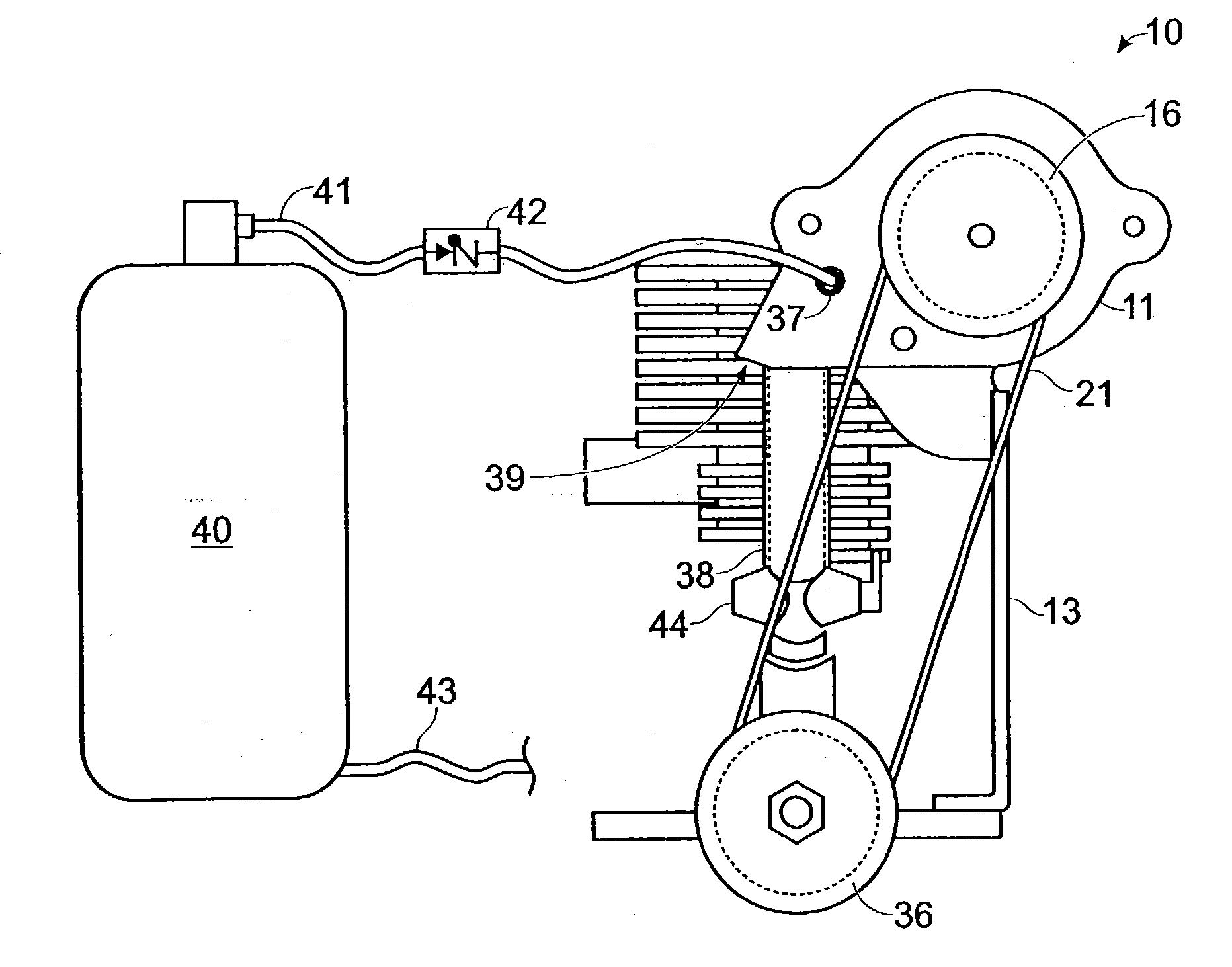
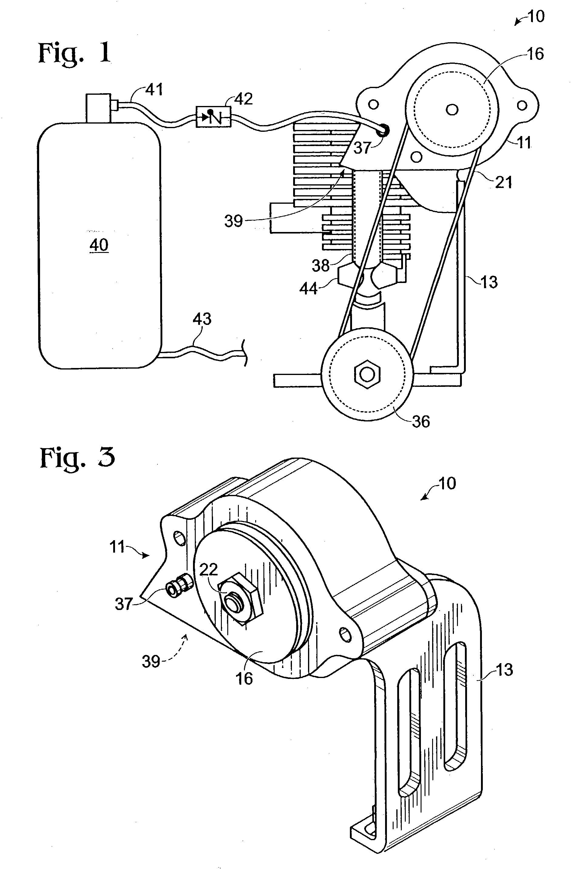
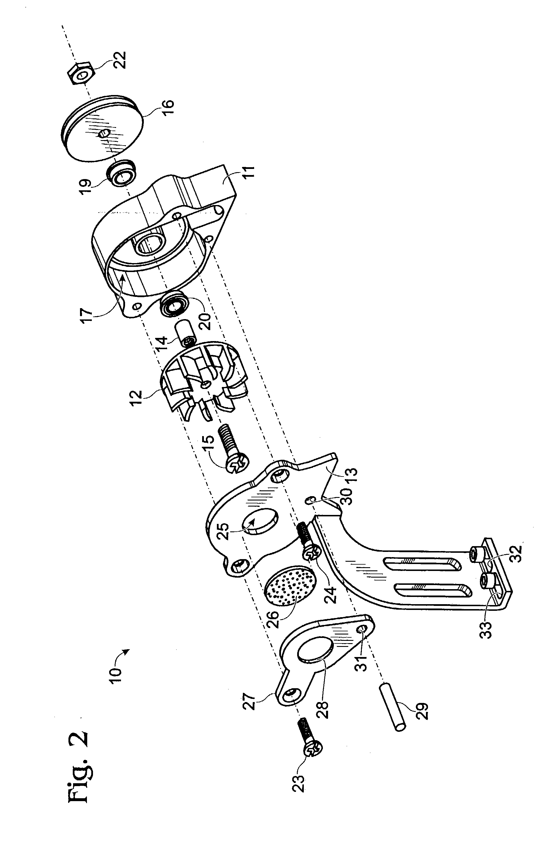
[0028] Referring now to FIG. 1, the supercharging device 10 is capable of being mounted on various types of model engines using the slots 34, 35 (FIG. 2) on the engine mounting bracket 13 for alignment. Standard model engines have a mounting flange on each side of the engine. Bolts 32, 33 (FIG. 2) are installed through slots 34, 35 of engine mounting bracket 13 securing supercharger assembly 10 to the given engine mounts. The spacing between the mounting holes 34, 35 varies for different engine types. The slots 34, 35 in the supercharging device's mounting bracket 13, however, allow the supercharging device 10 to be mounted on all standard types of model engines. The slots 34, 35 also allow for front to rear travel to align the drive pulley 16 on the supercharging device 10 to the engine pulley 36. In one embodiment, the standard engine flywheel is replaced with a modified flywheel in which the thickness has been reduced to accept a an engine pulley 36 that is the same thickness by ...


PUM


Abstract

A supercharger system for an internal combustion model engine is driven by the associated engine and includes a drive belt, a belt driven pulley and a mounting bracket. The pulley drives a shaft, which is connected to the turbo impeller. The impeller is driven at multiple speeds within a volute. The turbo impeller is recessed into an internal housing to provide smooth air flow from the impeller into the volute. The mounting bracket provides flexibility in mounting to various internal combustion model engines. A portion of the supercharger output pressure can be diverted through a hose containing a check valve and used to create positive pressure in a pressurized fuel cell, resulting in consistent and even flow of fuel into the engine's combustion chamber.

Description

FIELD OF THE INVENTION [0001] This invention relates to a boosting mechanism for use on internal combustion model engines, in particular to a supercharger for an internal combustion model engine and a fuel system boosting mechanism for an internal combustion model engine. As used in this specification, internal combustion model engine refers to a small internal combustion engine designed for use on scale model aircraft, scale model race cars, and small vehicles such as motorcycles, snowmobiles, go-carts, all-terrain vehicles and the like. The present invention enhances the power of model engines. BACKGROUND OF THE INVENTION [0002] Generally, an internal combustion model engine draws the air required for driving the engine by the negative pressure created as the engine is driven, which is sometimes referred to as scavenging. Also, fuel for such engines is delivered to the engine either by gravity feed from the fuel cell or by introducing pressure from exhaust gases into a pressurized...

Claims


Application Information

Patent Timeline
IPC IPC(8): F02B33/40F02B39/04F02B75/34F02M69/46H01M8/04
CPCF02B33/40F02B39/04F02B75/34Y02T90/32H01M8/04089H01M2250/20Y02E60/50F02M69/46Y02T90/40
Inventor BENSON, ROBERT C.
Owner BENSON ROBERT C
Why Eureka
Try Eureka