Liquid filtration apparatus and method embodying super-buoyant filtration particles

a technology of filtration apparatus and filtration particles, which is applied in the direction of sedimentation settling tank, multi-stage water/sewage treatment, separation process, etc., can solve the problems of inability to completely remove the cleaning process, the filtration process is more expensive, and the top surface of the bed is clogged with large particles, so as to achieve the effect of reducing the number of filtration and backwashing, reducing the number of filtration and filtration particles, and ensuring the effect o

Inactive Publication Date: 2005-02-10
SCHWARTZKOPF STEVEN H
View PDF41 Cites 55 Cited by
  • Summary
  • Abstract
  • Description
  • Claims
  • Application Information

AI Technical Summary

Benefits of technology

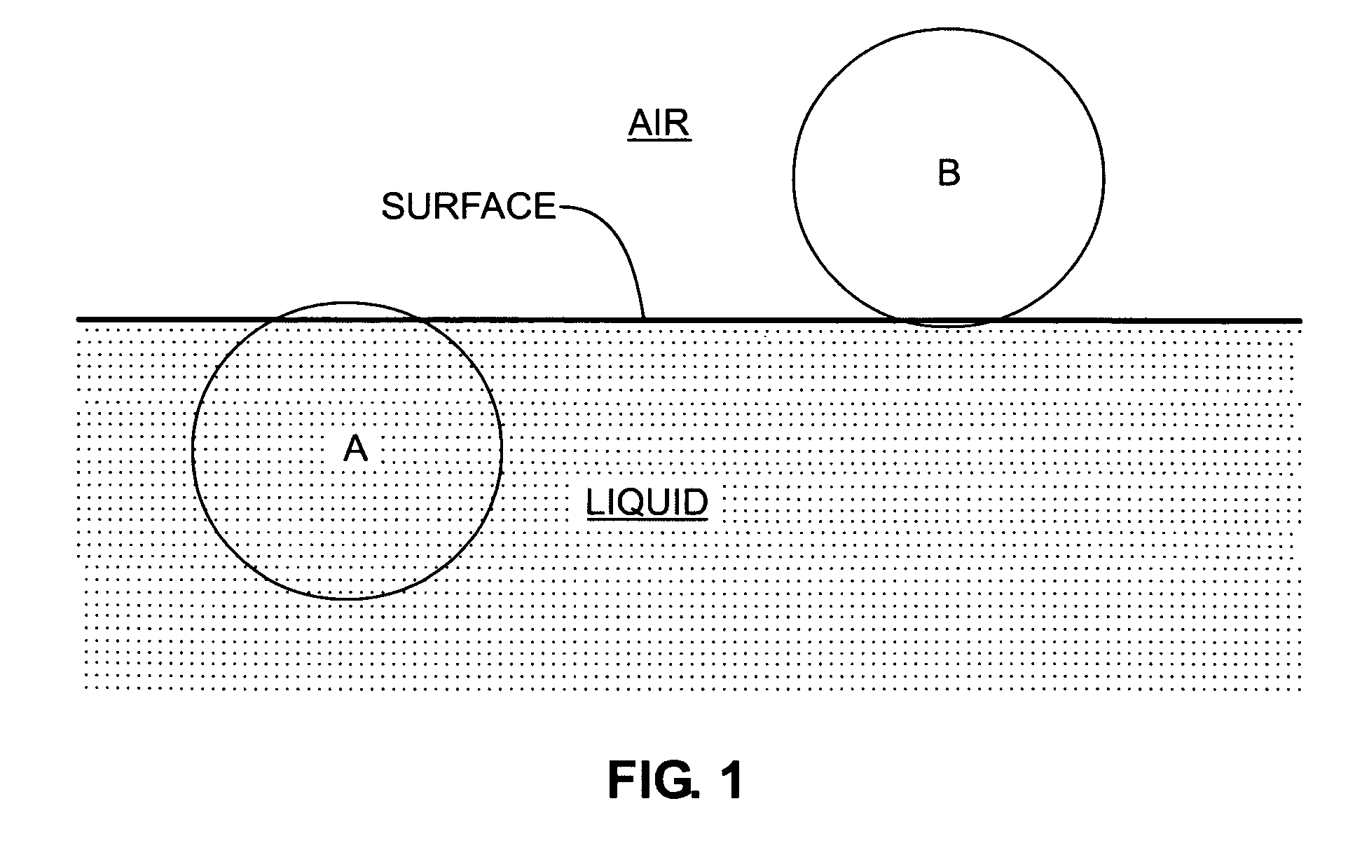
It must be emphasized that the distinction between filter media floating submerged beneath the surface of the process liquid and filter media floating on the surface of the process liquid is critical in determining the unique operational characteristics of the each kind of filter. For example, when using buoyant media in water, the filter media (A in FIG. 1) behave principally as though they are part of the water mass. Thus any horizontal movement of the water containing such media drags the media along with it. An injection of air bubbles into such a media bed will also move the media particles because they are very close to neutral buoyancy, and this neutral buoyancy renders them easy to move.
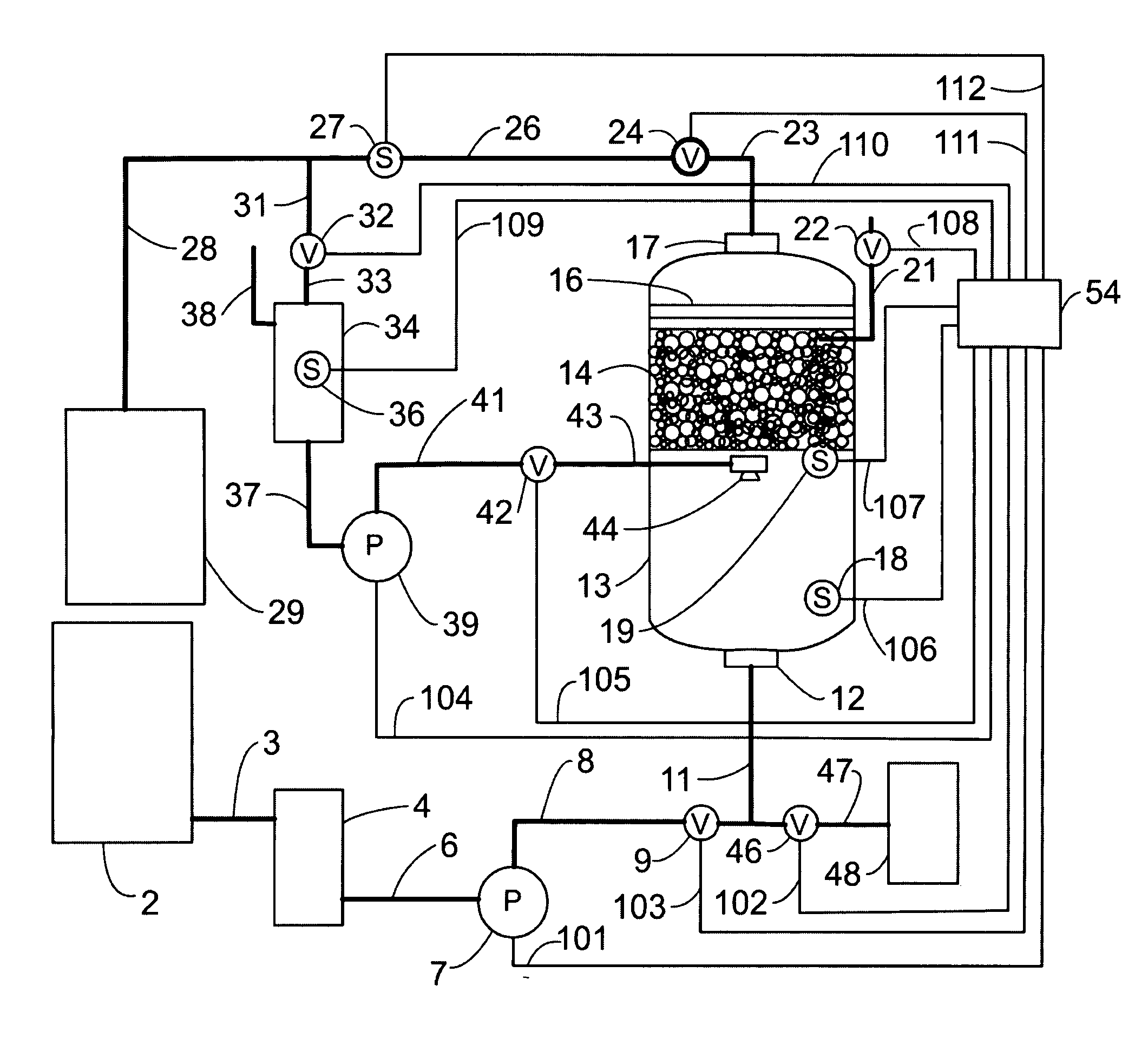
In a third aspect thereof, the present invention is directed to a liquid filtration apparatus that includes a backwash system that incorporates a backwash reservoir to store cleaned process liquid for backwashing, a backwash pump, a single or plurality of backwash nozzles, a backwash valve, and a backwash waste liquid / particulate collection reservoir. During the backwash cycle, stored cleaned process liquid is withdrawn from the backwash reservoir by the backwash pump and forced through the spray nozzles(s). This backwash spray, in conjunction with alternately opening and closing of the backwash valve at the bottom of the filter chamber, serves to efficiently clean the strained particulate contaminants from the bed and wash them into the waste liquid / particulate collection reservoir.

Problems solved by technology

However, even when the contaminant accumulation on the surface of such an element is removed, there are usually contaminant particles that remain lodged in the permeable element that cleaning is not totally successful in removing.
The more frequently such element replacement or stringent cleaning must be performed, the more costly this filtration process becomes.
First, the larger particulates, which are unable to pass through the spaces between the bed grains, are trapped at the top surface of the bed.
Ultimately, the particulates sequestered by the bed accumulate, making it more difficult for liquid to flow downward through the bed, and thus the flow rate declines.
Although sand and diatomaceous earth filters have been successfully applied to a wide variety of filtration problems, they have a number of limitations and drawbacks.
One of the most serious problems involves maintaining bed homogeneity during operation.
Inhomogeneities in the bed include, for example, cracks that offer regions of less flow resistance.
Such cracks lead to the formation of channels in the bed, poor distribution of the liquid flow through the bed, and thus very low particulate removal.
Such inhomogeneities may also allow air to be trapped in the bed, also leading to the formation of channels and poor distribution of the liquid.
On the other hand, beds composed of smaller particles can quickly become clogged with small contaminant particles, thus rendering the filter bed ineffective.
Microbes growing on these organic compounds can bind the filter particles together and clog the bed, thus decreasing its effectiveness and shortening the interval until cleaning.
To maintain cleanliness, large volumes of clean liquid are required to backwash and clean conventional filter beds, leading to large volumes of contaminated liquid which must be treated or properly disposed.
Even though backwashing is fairly effective for removing many of the particulates captured by the filter, some particulates may adhere so strongly to the bed particles that they are virtually impossible to remove.
These residual contaminants reduce the effectiveness of the filter and significantly impair filter performance.
In such circumstances, it is impossible to separate the heavy contaminant particles from the bed particles through a backwash process, and backwashing is therefore not effective as a cleaning method.
Thus, one of the most crucial problems with these systems, which is common knowledge to practitioners of this art, is the ineffectiveness of backwash systems for cleaning the filter media (i.e., Amirtharajah, 1978).
As a consequence, in many situations, the contaminated bed cannot be cleaned and instead must be replaced with new bed material.
In applications that involve heavy particulate contaminant loads in the process liquid, these media may have to replaced on a daily or weekly basis, which is not economical.
Due to the relatively large size of the media particles, these buoyant media filter beds are not optimized to remove small particulate contaminants.
The requirement to use a “ripened” filter media bed dictates that the performance and operation of the media bed cannot be accurately characterized or predicted, as both depend on the amount and nature of the contaminant material(s) previously deposited on the buoyant media particles during the ripening process.
This lack of predictable operation makes it very difficult or impossible to develop an optimal design for this type of filter.
If the backwash is especially vigorous, particles that were adhering to the buoyant media will be removed from the media and a portion of the buoyant media's filtration capacity would thus be lost.
However, because the media particles have a specific gravity close to that of water, they are moved easily by the backwash mechanism, and cannot be thoroughly cleaned.
Unfortunately the problems encountered in using small diameter non-buoyant media, such as sand or diatomaceous earth, are exacerbated when using small diameter buoyant media.
Due to the high surface area of the small diameter media, contaminant particles that fill the interstices between the media particles can act like a glue which makes the media particles adhere to one another and form clumps which lead to the formation of non-homogeneities within the bed (just like the problem that occurs in small diameter non-buoyant media).
Because the backwash systems must be relatively gentle in nature for the filter to retain its “ripened” state, these non-homogeneities cannot be removed from the bed, and the bed performance declines.
This problem dictates that small diameter filter media not be used in buoyant media applications, because the ripening process itself severely limits the efficacy of the filter bed.
In addition, for cost savings, many of these buoyant media filter systems do not employ a separate backwash pump or backwash water storage system.
In these designs, maximum cleanliness of the media particles cannot be achieved because a separate, isolated pump and process liquid storage system are not utilized to provide a source of clean process liquid for backwashing.
Thus, although such buoyant media filters have desirable characteristics for specific filtration applications, they do not overcome the above-stated disadvantages of conventional media bed filters.

Method used


Image

  • Liquid filtration apparatus and method embodying super-buoyant filtration particles
  • Liquid filtration apparatus and method embodying super-buoyant filtration particles
  • Liquid filtration apparatus and method embodying super-buoyant filtration particles

Examples


Embodiment Construction

Single Filter Housing Embodiment

In this embodiment (FIG. 7), a central control system designated generally by the numeral 54 is used to monitor the sensors installed in the filtration system, and to turn “ON” and “OFF” all of the actuators (pumps and valves) required to operate the system. This control system may be operated either by manually actuated switches or by electronic switches activated by an embedded microprocessor. Although using a microprocessor makes the system somewhat more complex, it enables more efficient operation of the system as well as providing unattended operating capability during periods when no personnel are available to manually control the system.

During normal operation, the process liquid to be filtered is withdrawn from a reservoir 2, connected by a conduit 3, to a pump priming chamber 4. Alternatively, the liquid may also be withdrawn directly from a process liquid stream. Although not absolutely required, the use of the pump priming chamber 4 he...


PUM

PropertyMeasurementUnit
specific sizeaaaaaaaaaa

Abstract

Presented is a liquid filtering apparatus and method that overcomes the disadvantages encountered with prior bed filtration systems by providing a filtering apparatus that incorporates a super-buoyant filter medium having a specific gravity very substantially lower than that of the process liquid being filtered. This feature enables a majority of the medium to float on top of the process liquid. Due to the significant differences in specific gravity between the media and the process liquid, super-buoyant media produce a highly advantageous means of naturally, gravimetrically separating both clean and contaminated filter media and process liquid into separate “phases”. Under normal filtering operation, the filter media is contained within a filter housing by a bed support near the top of the filter housing, and particulate material is filtered from a process liquid that passes through the housing. To regenerate the filter media, the housing is drained and a nozzle creates a backwash spray that washes the particulate material from the filter media. During the backwash process, the filter media rises past the nozzle as the level of the backwash liquid in the housing rises, so that the entire filter media is regenerated.

Description

BACKGROUND OF THE INVENTION 1. Field of the Invention The present invention relates to an apparatus and method for filtering particulates of various sizes from miscellaneous process liquids, and more particularly to an apparatus and method that utilizes a filtration bed formed from super-buoyant media, which has a specific gravity much lower than that of the liquid being filtered. 2. Description of the Prior Art A preliminary patentability and novelty search regarding the invention described herein has revealed the existence of the following United States Patents: 3,067,3583,469,0573,678,2403,709,3623,962,5574,032,3004,198,3014,383,9204,387,2864,415,4544,417,9624,608,1814,743,3824,839,4884,865,7344,883,0834,952,7674,963,2575,030,3535,122,2875,126,0425,178,7725,217,6075,227,0515,232,5865,573,6635,747,3115,770,0805,833,8675,932,0925,945,0056,015,497 A careful review of the patents noted above has failed to reveal the concept, apparatus and method disclosed herein. The need to re...

Claims


Application Information

Patent Timeline
Patent Type & Authority Applications(United States)
IPC IPC(8): B01D21/00B01D24/16C02F1/00C02F1/32
CPCB01D21/0012B01D24/165C02F1/004C02F1/32C02F2101/20C02F2103/42C02F2103/16B01D24/36B01D24/4636Y02A20/152
Inventor SCHWARTZKOPF, STEVEN H.
Owner SCHWARTZKOPF STEVEN H
Why Eureka
Try Eureka