
Electro-optical device and driving method thereof, projection-type display device, and electronic apparatus

a technology of optical devices and electronic devices, applied in the direction of instruments, color television details, television systems, etc., can solve the problems of non-uniform luminance problems, easy crosstalk, etc., and achieve the effect of non-uniform brightness of upper and lower regions of the screen

Inactive Publication Date: 2005-02-10
SEIKO EPSON CORP
View PDF5 Cites 14 Cited by
  • Summary
  • Abstract
  • Description
  • Claims
  • Application Information

AI Technical Summary

Benefits of technology

[0006] However, in the case of the field-inversion driving method, crosstalk can easily occur due to the high voltage variation during the holding period. In addition, non-uniform luminance problems can occur in the up-down direction of a liquid crystal display panel. In other words, for one data line of the field-inversion driving method, the image signal with same polarity is written in from a field for all pixels where the signal is provided from the corresponding data line. In addition, the polarity of the image signal that is provided to the corresponding data line is inversed once it is moved to the next field. At that time, when the scanning line is scanned from top to bottom of an image display region, the image signal is written in the upper pixels in the display region. And then, the polarity of the image signal that is applied in the corresponding data line has the same polarity as the electric potential of the pixel during most of time of the holding period. However, after the image signal is written in the lower pixels, the image signal having a polarity opposite to the electric potential of the pixel is applied in the data line during most of the holding period. As a result, the leaking voltage through the off-resistance of a switching element increases as much as that of the lower pixel in the screen, resulting in non-uniform brightness of upper and lower regions in the screen.
[0007] It is an aspect of the invention to provide an electro-optical device and a driving method thereof, a projection-type display device, and electronic apparatus that is possible to improve the display quality of moving picture while obtaining the display uniformity in the screen by suppressing the crosstalk.
[0008] An electro-optical device according to the invention can include a plurality of pixels are arranged in an image display region and a driving circuit unit for driving the pixels in a matrix. The driving circuit unit divides one frame into a plurality of continuous fields, one of data of two continuous fields being image data and the other being black display data. The data of the two continuous fields is alternately written in every one horizontal period while changing the starting time of the writing-in of each field within one vertical period, and the polarity of data signals is inversed between the two continuous fields centering a predetermined electric potential. The invention makes it possible to execute an impulse-type display by installing the black display field in a frame (that is, insert a black image in the image).

Problems solved by technology

However, in the case of the field-inversion driving method, crosstalk can easily occur due to the high voltage variation during the holding period.
In addition, non-uniform luminance problems can occur in the up-down direction of a liquid crystal display panel.
As a result, the leaking voltage through the off-resistance of a switching element increases as much as that of the lower pixel in the screen, resulting in non-uniform brightness of upper and lower regions in the screen.

Method used


Image

  • Electro-optical device and driving method thereof, projection-type display device, and electronic apparatus
  • Electro-optical device and driving method thereof, projection-type display device, and electronic apparatus
  • Electro-optical device and driving method thereof, projection-type display device, and electronic apparatus

Examples


Embodiment Construction

[0040] Hereinafter, a first preferred embodiment of the invention will be described in detail with reference to the FIGS. 1 to 10.

[0041] In the present embodiment, a liquid crystal light valve (liquid crystal device) that is used as an optical modulator of a projection-type display device among the electro-optical devices will be described by taking an example.

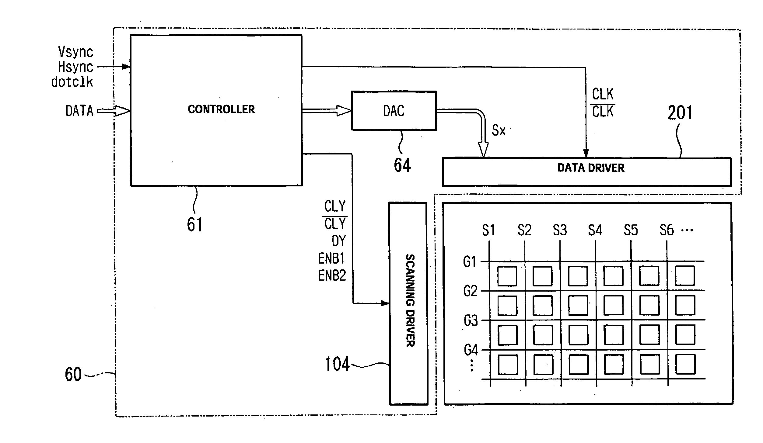
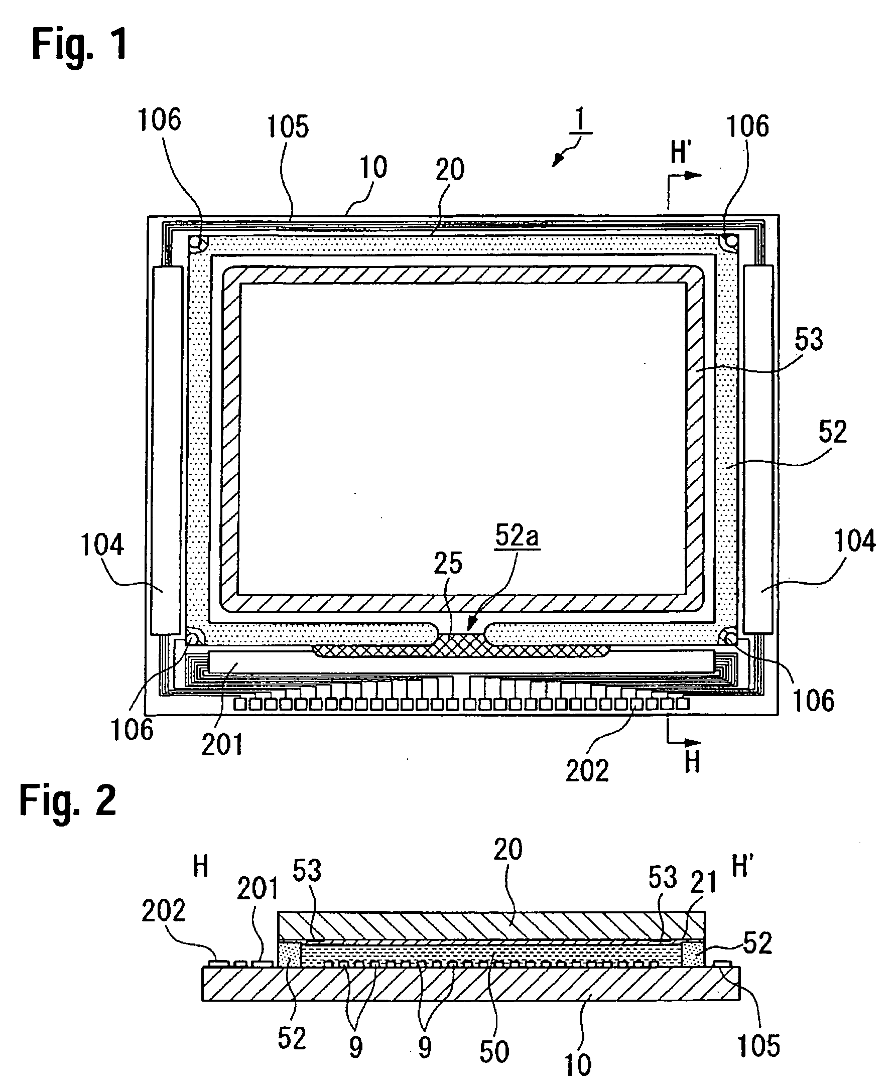
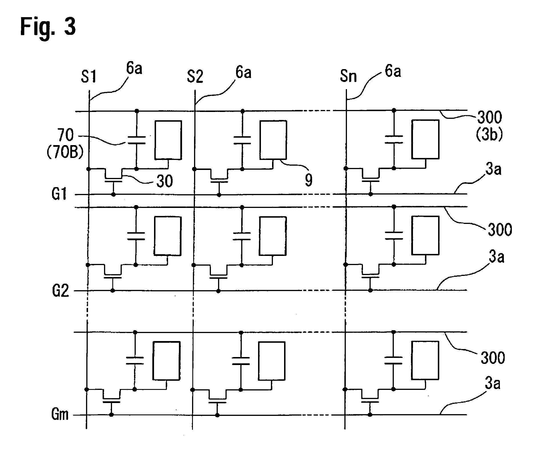
[0042]FIG. 1 shows the schematic structure of a liquid crystal light valve according to an embodiment of the invention. FIG. 2 shows a cross-sectional view taken along the line H-H′ of FIG. 1. FIG. 3 shows an equivalent circuit of the plurality of pixels that constitute the liquid crystal light valve and are formed in a matrix. FIG. 4 shows a block diagram including a driving circuit unit. FIG. 5 shows a circuit diagram that represents the structure of a scanning driver in the driving circuit unit. FIG. 6 shows the detailed circuit diagram of the main part of FIG. 5. FIG. 7 shows a timing chart illustrating the operation of ...


PUM


Abstract

An exemplary embodiment provides an electro-optical device having an improved display quality of moving picture, while obtaining the display uniformity in a screen by suppressing a crosstalk. The electro-optical device according to the invention can include a plurality of pixels are arranged in an image display region and a driving circuit unit for driving the pixels in a matrix. The driving circuit unit divides data of one frame into a plurality of data corresponding to a plurality of fields, one of data of two continuous fields being image data and the other being black display data. The data of the two continuous fields is alternately written in every one horizontal period while changing the starting time of the writing-in of each field within one vertical period, and the polarity of data signal is inversed fields against a predetermined electric potential between the two continuous. As a result, the image display region and black display region are simultaneously formed in a screen, and then the execution of a pseudo impulse-type display can be performed. Further, the occurrence of discrimination can be avoided since the pseudo field-inversion driving is executed every region. On the other hand, the crosstalk can be avoided since a line-inversion driving can be executed for the data line.

Description

BACKGROUND OF THE INVENTION [0001] 1 Field of Invention [0002] The present invention relates to an electro-optical device and driving method thereof, projection-type display device, and electronic apparatus. More specifically, the invention relates to an electro-optical device that is suitable for a liquid crystal light valve mounted on the projection-type display device, and its driving method. [0003] 2. Description of Related Art [0004] In related electro-optical devices, such as liquid crystal displays (LCDs), a blurring phenomenon that makes an image contour unclear can occur during the display of moving picture. The cause of the blurring phenomenon was thought to be a poor responsiveness of the liquid crystal. However, it has been recently been determined that the reason is due to the hold-type driving method in itself that continuously displays image. In the hold-type display devices, the previous image is continuously displayed until the image changes, while one observes the ...

Claims


Application Information

Patent Timeline
IPC IPC(8): G02F1/133G09G3/00G09G3/20G09G3/34G09G3/36H04N5/66
CPCG09G3/3614G09G3/3648G09G2320/0261G09G2320/0209G09G2320/0233G09G3/3677
Inventor HOSAKA, HIROYUKI
Owner SEIKO EPSON CORP
Learn More