Transmitter and method for digital multi-carrier transmission

a multi-carrier transmission and transmitter technology, applied in digital transmission, secret communication, electrical equipment, etc., can solve the problems of poor resistance to narrow band interference, low transmission efficiency, poor resistance to internal interference, etc., to improve the convergence speed of agc and shorten the length of preamble data

Active Publication Date: 2005-02-10
PANASONIC CORP
View PDF11 Cites 25 Cited by
  • Summary
  • Abstract
  • Description
  • Claims
  • Application Information

AI Technical Summary

Benefits of technology

[0008] In this way, the invention provides a transmitter and transmitting method which enables shortening of the length of the preamble data and improves the convergence speed of the AGC.

Problems solved by technology

Recently, wavelet-based OFDM has been proposed to replace FFT-based OFDM as a modulation / demodulation method in OFDM transmission because FFT-based OFDM has basic weaknesses such as poor resistance to narrow band interference, poor resistance to internal interference, and low transmission efficiency because of the necessity of a cyclic prefix.
While auto gain control (AGC) is performed in a receiver by using a wavelet waveform without ramp processing, convergence speed of the AGC becomes an issue because of the complexity of the wavelet waveform.

Method used


Image

  • Transmitter and method for digital multi-carrier transmission
  • Transmitter and method for digital multi-carrier transmission
  • Transmitter and method for digital multi-carrier transmission

Examples


first embodiment

[0025] A first embodiment of the invention generates a digital wavelet multi-carrier (DWMC) transmission signal from a plurality of digitally modulated waves that are received from real-coefficient filter banks. Low bit rate modulation, such as quadrature phase shift keying (QPSK), quadrature amplitude modulation (QAM) or pulse amplitude modulation (PAM), may be used for modulating each carrier.

[0026] A data transmission method according to the DWMC transmission method will be described with reference to FIGS. 4 and 10-12.

[0027]FIG. 10 illustrates a waveform of a wavelet, and FIG. 11 illustrates a DWMC transmission waveform according to the invention. As shown in FIG. 10, each waveform 1001 of the wavelet has an impulse response, and impulse responses of each of the plurality of waveforms 1001 are transmitted in an overlapping relationship with each other. As shown in FIG. 11, each transmission symbol 1101 is formed by a time waveform 1102 that is a combination of impulse response...

second embodiment

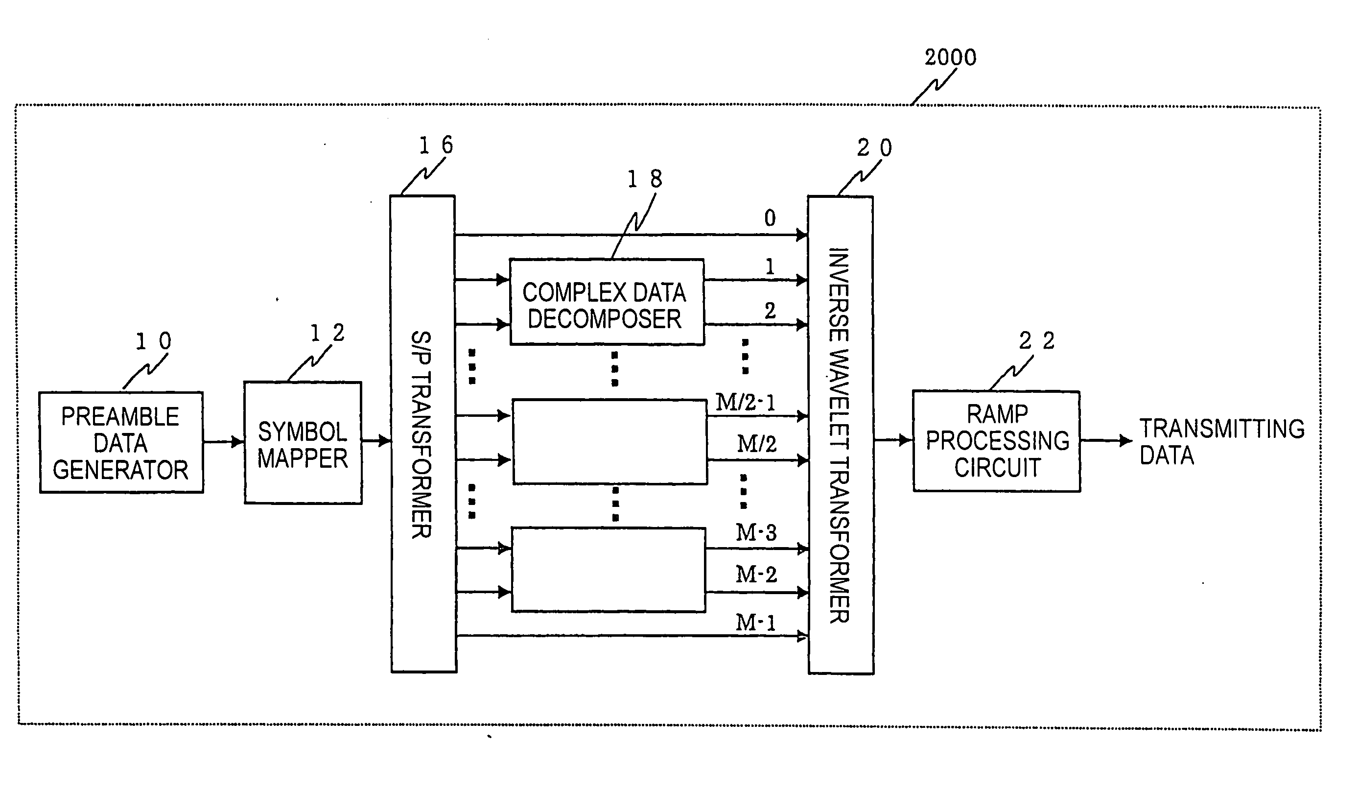
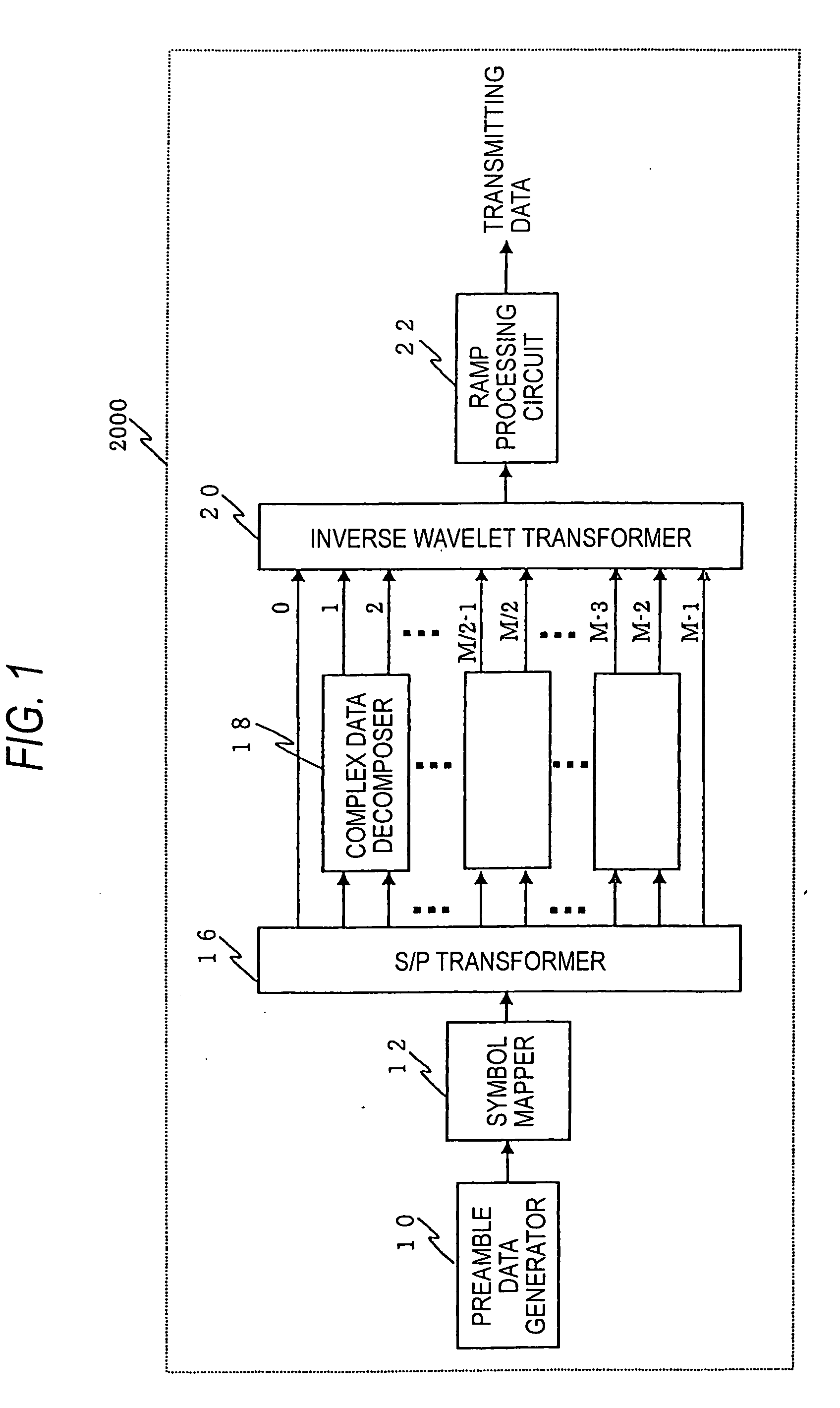
[0044] A transmitter of the second embodiment basically has the same configuration as the transmitter of the first embodiment. However, the ramp processing is different from that employed in the transmitter of the first embodiment. This difference will be described in detail with reference to FIGS. 1, 3-5, and 16.

[0045] In the present embodiment, preamble data generator 10 normally outputs serial data having values of “0” until instructed by the controller to output preamble data. When the instruction is received to output preamble data, preamble data generator 10 serially generates a value, such as “1,” over several symbol periods so that each subcarrier produced by S / P transformer 16 contains a series of this value as its preamble data.

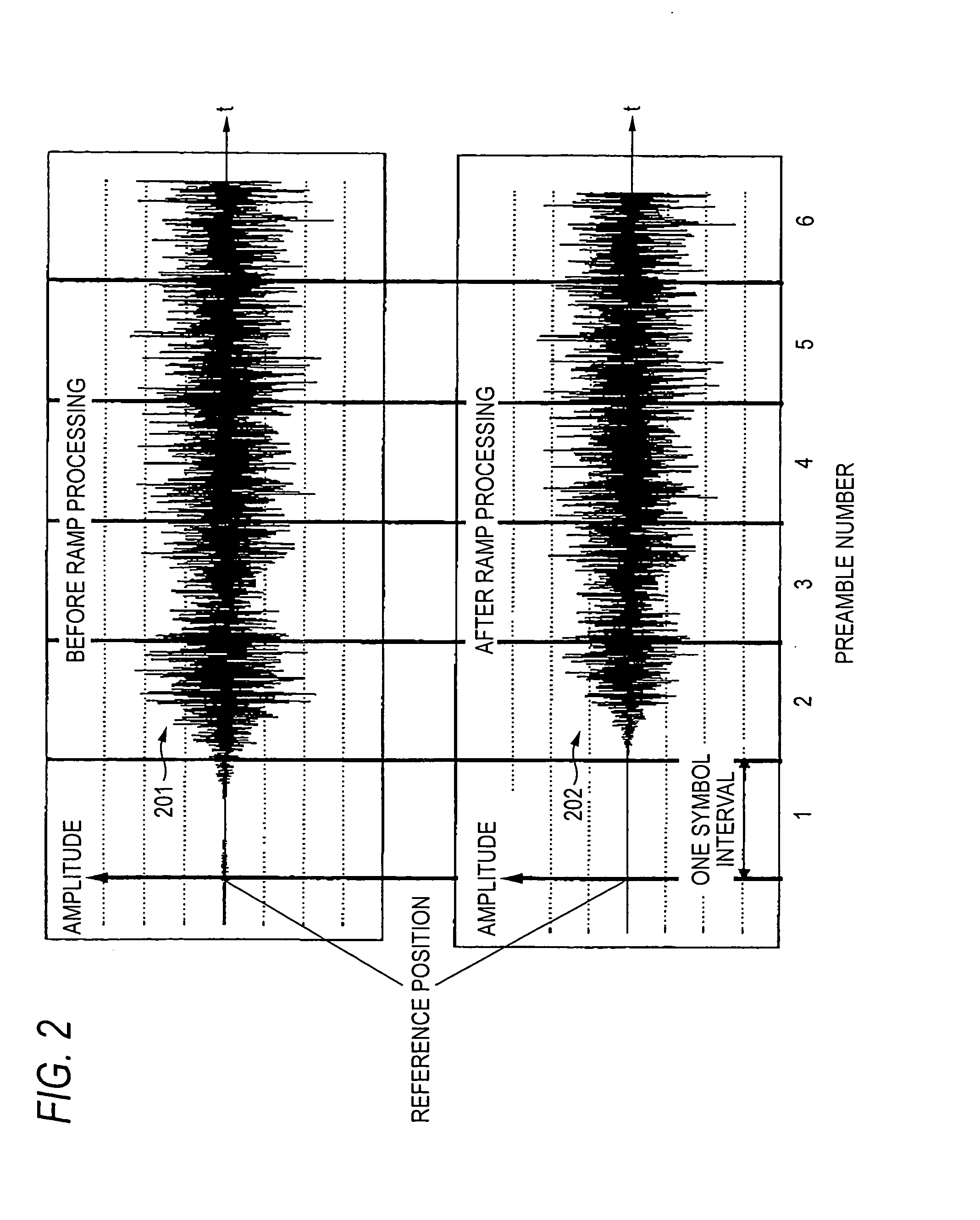
[0046]FIG. 9 illustrates a relationship among symbol data 901 of the Preamble data, a time waveform 902 of the preamble data, and a ramp processing waveform 903 used for generating a DWMC transmission signal according to the invention. In FIG. 9, ...

third embodiment

[0055] A transmitter of the third embodiment has basically the same configuration as the transmitter of the first embodiment. However, the configuration of the inverse wavelet transformer 20 will be described in greater detail here, with reference to FIGS. 6-8.

[0056]FIG. 6 illustrates a block diagram of an inverse wavelet transformer in a transmitter according to a third embodiment of the invention. Inverse wavelet transformer 20 includes a fast discrete cosine transformer (type 4)40, a prototype filter 42, M up-samplers 44, and M-1 delays 46. Up-samplers 44 multiply the sampling rate of the transmitted waveform by M, and delays 46 delay the transmitted waveform.

[0057]FIG. 7 illustrates a block diagram of a prototype filter 42 of the inverse wavelet transformer according to the third embodiment of the invention. Prototype filter 42 is a polyphase filter that includes multipliers 62, which hold prototype filter coefficients, and adders 64. A general configuration of a polyphase fil...


PUM


Abstract

The present invention relates to a transmitter and method employing a multi-carrier transmission method, especially utilizing real coefficient wavelet filter banks. The transmitter includes a preamble data generator, a modulator, and a ramp processor. The preamble data generator generates preamble bit data, and outputs the preamble data. The modulator modulates the preamble data, generates a plurality of subcarriers, and outputs a composite wave of the time waves of the plurality of subcarriers. Subsequently, the ramp processor performs ramp processing on the composite wave with a certain delay period from a reference position of the composite wave.

Description

BACKGROUND OF THE INVENTION [0001] 1. Field of the Invention [0002] The present invention relates to a transmitter and transmission method employing a multi-carrier transmission technique, particularly a digital wavelet multi-carrier (DWMC)transmission technique utilizing real coefficient wavelet filter banks. [0003] 2. Description of the Related Art [0004] Orthogonal frequency division multiplexing (OFDM) is frequently adopted as a conventional multi-carrier transmission method, for example, as described in U.S. Pat. No. 6,442,129. In the OFDM transmission method, discrete Fourier transform (DFT), particularly fast Fourier transform (FFT), is adopted as a modulation / demodulation method. In addition, in FFT-based OFDM, generally speaking, ramp processing is adopted, which makes the time waveform on a leading edge of a frame (preamble) smooth in order to prevent the waveform from distorting in a transmission channel or in hardware such as an amplifier. [0005] Recently, wavelet-based ...

Claims


Application Information

Patent Timeline
Patent Type & Authority Applications(United States)
IPC IPC(8): H04L27/00H04L27/26
CPCH04L27/0004H04L27/2602H04L27/2642H04L27/264H04L27/2639H04L27/26416
Inventor KOGA, HISAOKODAMA, NOBUTAKA
Owner PANASONIC CORP
Why Eureka
Try Eureka