Multi-layer conductive/insulation pad

a conductive/insulation pad and multi-layer technology, applied in heat-proofing, synthetic resin-layered products, transportation and packaging, etc., can solve the problems of reducing the performance of radiantly heated slabs, reducing the reflectivity of foils, and not being entirely effective in the ar

Inactive Publication Date: 2005-02-10
SEALED AIR U S
View PDF16 Cites 36 Cited by
  • Summary
  • Abstract
  • Description
  • Claims
  • Application Information

AI Technical Summary

Benefits of technology

[0015] Yet another object of the present invention is to provide a concrete pad in which the insula

Problems solved by technology

INVENTIONDespite numerous attempts to provide an effective product that can be used to insulate under concrete slabs, the materials presently used in the art are not altogether effective.
It has been found that this theory is incorrect as it is a well-known fact that coating the foil surface or applying a f

Method used


Image

  • Multi-layer conductive/insulation pad
  • Multi-layer conductive/insulation pad

Examples


first embodiment

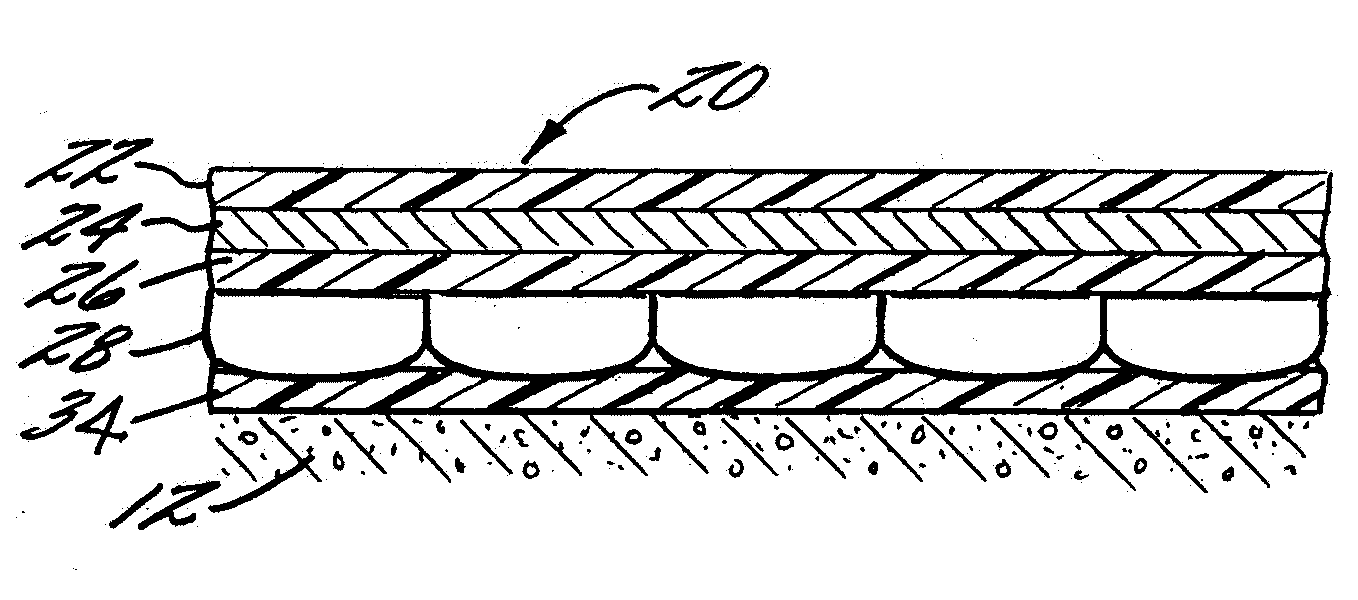
[0008] In accordance with the present invention, there is provided a multi-layered conductive / insulation pad. In the invention a multi-layer conductive / insulation pad is provided having, in order, a first polymer layer, a conductive layer, such as a thin foil of metal or a metallized thermoplastic film, laminated to the first polymer layer, a second polymer layer laminated to the side of the conductive layer opposite the side of the first polymer layer. At least one bubble wrap layer is laminated to the side of the second polymer film opposite the conductive layer. Optionally, a protective polymer layer is laminated to the first bubble wrap layer on the opposite side of the second polymer layer. The first and second polymer layers are laminated to the opposite sides of the conductive layer to protect the layer from oxidizing and to protect the layer from the lime in the curing concrete, and, when used directly on the soil, the alkali content in the soil. The insulation componen...

second embodiment

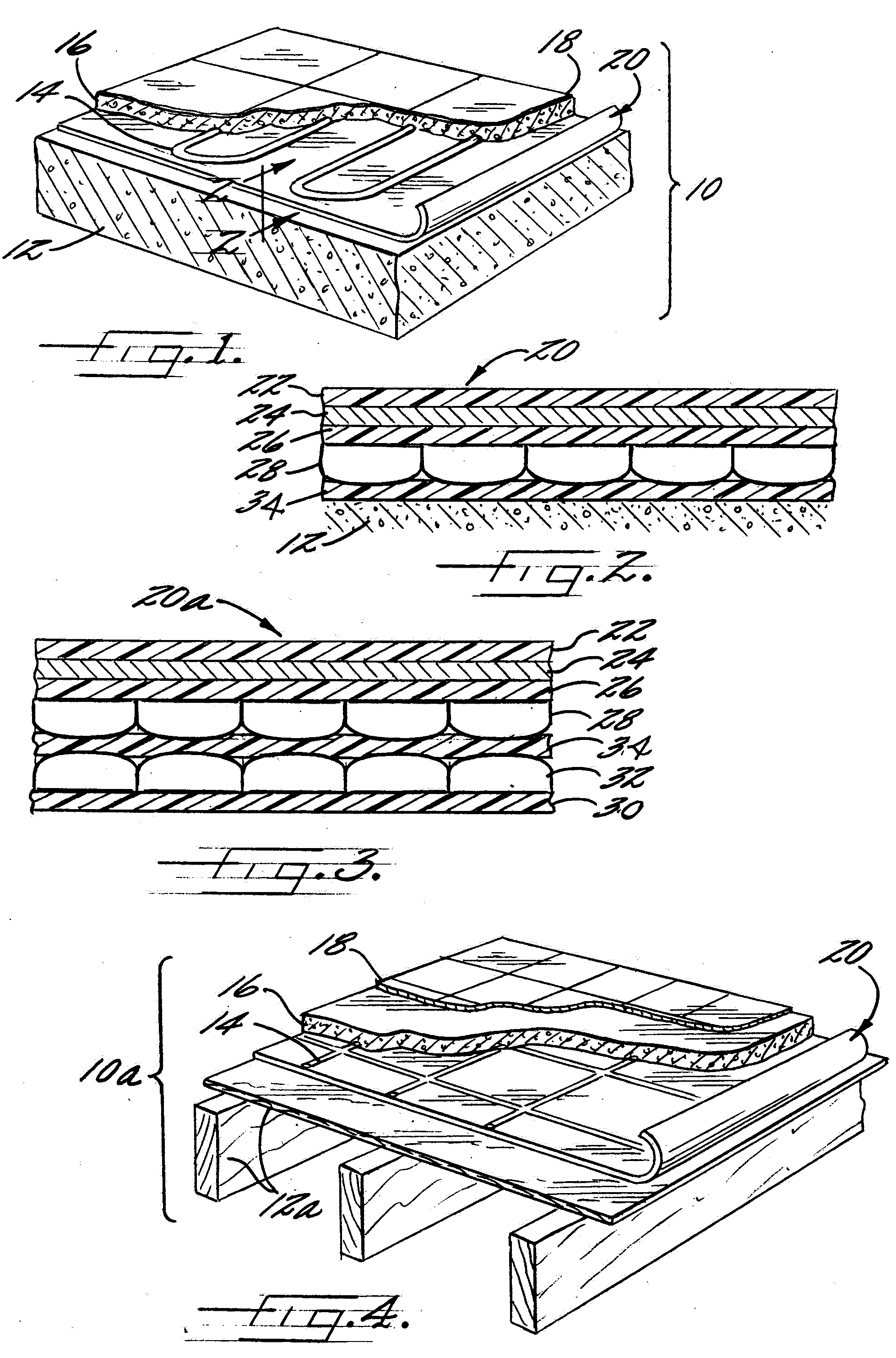
[0020]FIG. 3 is a diagramic enlarged sectional view of the conductive / insulation pad of the present invention also taken along line 2-2 of FIG. and

[0021]FIG. 4 is another perspective view in partial section of the conductive / insulation pad of the present invention illustrating use in another environment.

Detailed Description

[0022] The present inventions now will be described more fully hereinafter with reference to the accompanying drawings, in which some, but not all embodiments of the invention are shown. Indeed, these inventions may be embodied in many different forms and should not be construed as limited to the embodiments set forth herein; rather, these embodiments are provided so that this disclosure will satisfy applicable legal requirements. Like numbers refer to like elements throughout.

[0023] Referring more particularly to the drawings, there is shown in FIG. 1 a perspective view of a radiant heating assembly 10 showing a conductive / insulation pad 20 overlaying the grou...


PUM

PropertyMeasurementUnit
Densityaaaaaaaaaa
Electrical conductoraaaaaaaaaa

Abstract

Abstract of the Disclosure
There is provides a multi-layer conductive/insulation pad is provided having a first polymer layer, a conductive layer such as a thin foil of metal or a metallized thermoplastic film laminated to the first polymer layer, a second polymer layer laminated to the side of the conductive layer opposite the side of the first polymer layer, and a first bubble wrap layer. The first bubble wrap layer is laminated to the side of the second polymer film opposite the conductive layer. Optionally, a protective heavy-duty polymer layer is laminated to the first bubble wrap layer on the opposite side of the second polymer layer. In another embodiment the multi-layer construction of pad of the first embodiment has added thereto a third polymer layer laminated to the side opposite the first layer of bubble wrap and a second layer of bubble wrap laminated to the third polymer layer on the side opposite the first bubble wrap. Optionally, a protective heavy-duty polymer layer is laminated to the first bubble wrap layer on the opposite side of the second polymer layer.

Description

Detailed Description of the InventionBackground of Invention[0001] FIELD OF THE INVENTION.The present invention relates generally to a multi-layer conductive / insulation material. More particularly, this invention relates to a multi-layer pad having both conductive and insulating properties that is particularly suitable for use under a concrete slab.[0002] DESCRIPTION OF THE PRIOR ART.Materials to control the movement of heat have been used for many years and in many forms depending upon the desired use. For example, a variety of materials such as sawdust, straw, wool blankets and bats of foam or fiberglass have been used for insulation. However, special uses require materials having special insulating characteristics. One of these special uses is to prevent radiant heat transfer under concrete slabs. In many parts of the country houses, driveways and the like are constructed on concrete slabs laid either directly on the ground or on sub-flooring. Many of these types of struct...

Claims


Application Information

Patent Timeline
IPC IPC(8): B32B27/08E02D27/01E04B1/78E04F15/18
CPCB32B27/08E02D27/01Y10T428/24661E04F15/18E04B1/78E04F15/182B32B15/08B32B2307/206B32B2307/202B32B15/20B32B27/20
Inventor KANNANKERIL, CHARLESTOKARSKI, DALE
Owner SEALED AIR U S
Why Eureka
Try Eureka