Molded article located in the beam path of radar device, and method of manufacturing the same

a radar device and beam path technology, applied in the field of molded articles, can solve the problems easy peeling off of indium film, etc., and achieve the effects of large radio transmission loss, lack of durability, and easy peeling o

Inactive Publication Date: 2005-02-10
TOYOTA JIDOSHA KK
View PDF10 Cites 15 Cited by
  • Summary
  • Abstract
  • Description
  • Claims
  • Application Information

AI Technical Summary

Benefits of technology

[0010] While the indium film, which provides a metallic color, is suitable for the coating of the emblem or the like, it has a large radio transmission loss. Therefore, if it is mounted in front of the radar device, the beam from the radar device is attenuated. An indium film easily peels off and lacks in durability. Moreover, indium is a metal and is therefore subject to potential corros

Problems solved by technology

While the indium film, which provides a metallic color, is suitable for the coating of the emblem or the like, it has a large radio transmission loss.
An indium film easily peels off and lac

Method used


Image

  • Molded article located in the beam path of radar device, and method of manufacturing the same
  • Molded article located in the beam path of radar device, and method of manufacturing the same
  • Molded article located in the beam path of radar device, and method of manufacturing the same

Examples


Embodiment Construction

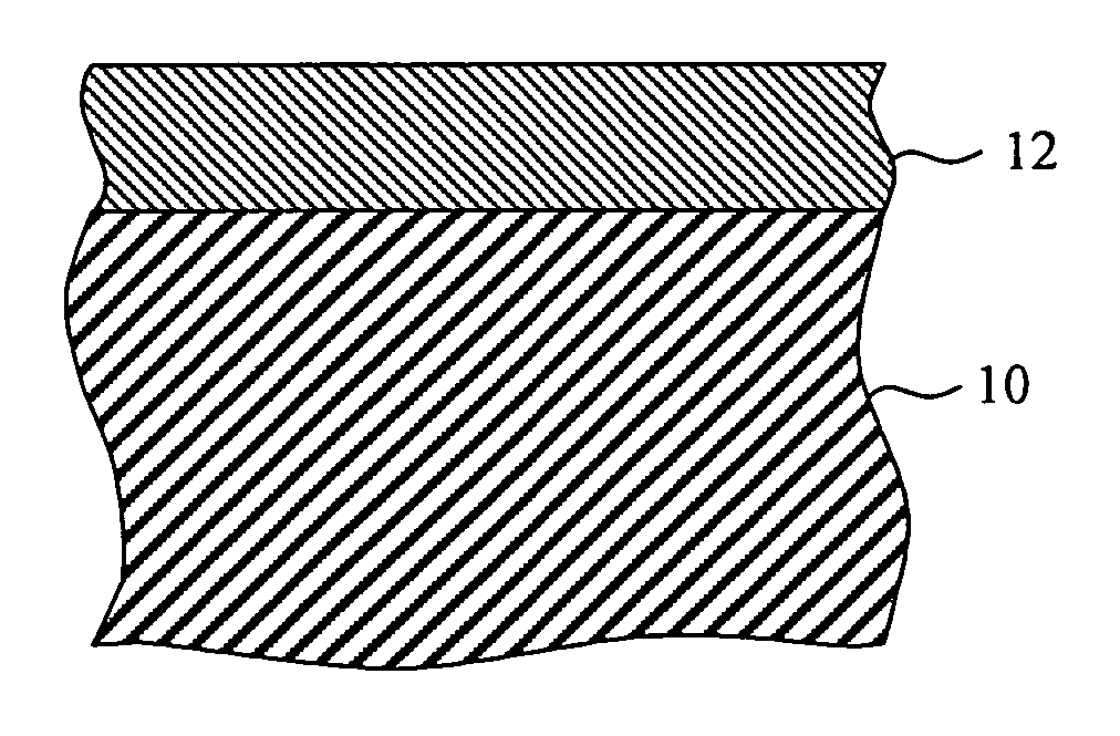
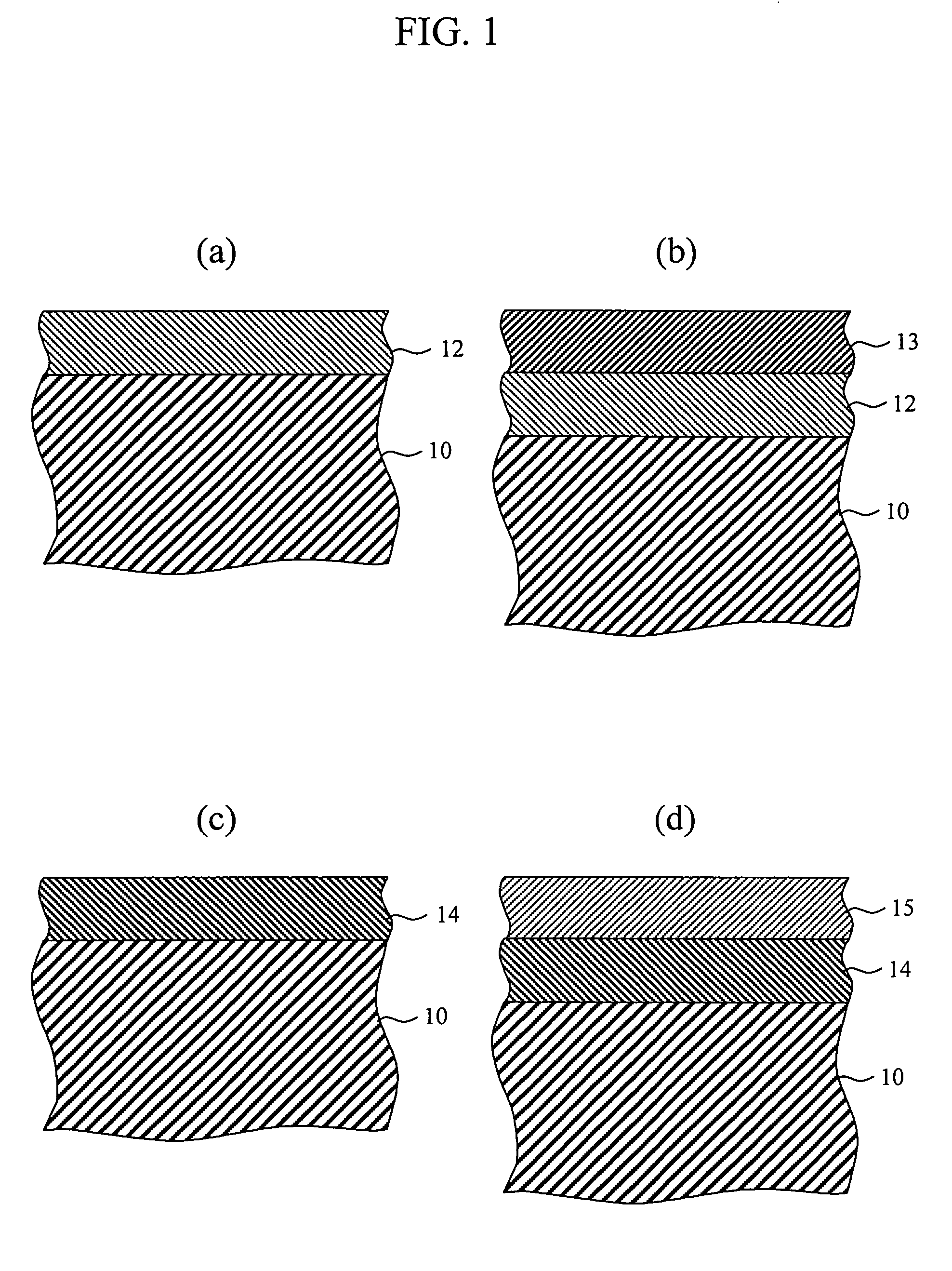
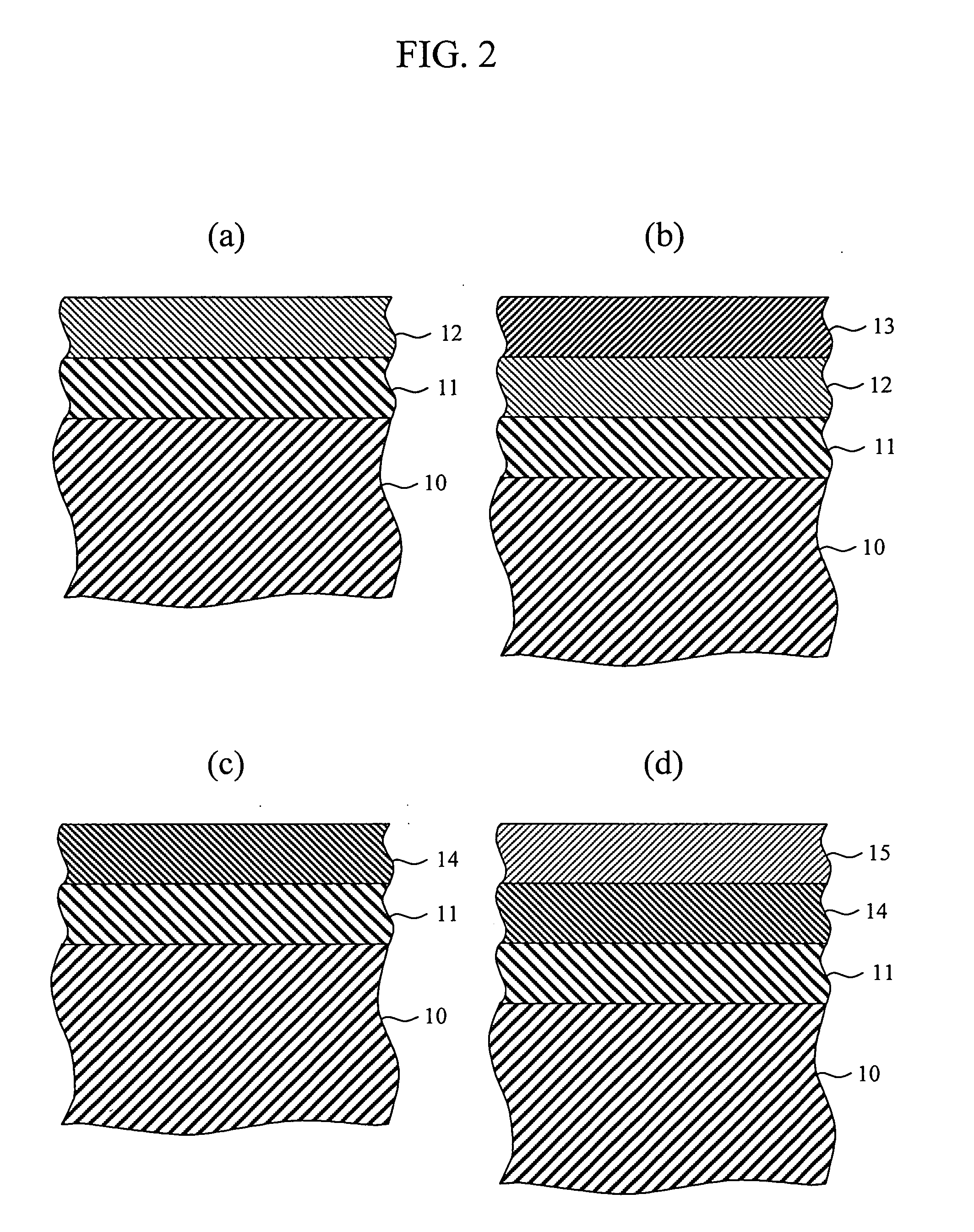
[0027]FIGS. 1 and 2 show cross sections of the surface of a molded article according to the invention that is located in the beam path of a radar device. FIG. 1(a) shows a first example of the invention. In this example, the molded article comprises a substrate 10 and a layer 12 of ceramic material that is disposed on the substrate 10. The ceramic material layer 12 may be made of nitride ceramics, oxide ceramics, or carbide ceramics. Examples of the nitride ceramics include titanium nitride TiN, aluminum nitride AlN, chromium nitride CrN, silicon nitride Si3N4, iron nitride FeN, gallium nitride GaN, and zirconium nitride ZrN. Examples of the carbide ceramics include silicon carbide SiC, titanium carbide TiC, zirconium carbide ZrC, boron carbide B4C, and tungsten carbide WC.

[0028] In the present example, the ceramic material layer 12 is preferably made from titanium nitride TiN or aluminum nitride AlN.

[0029]FIG. 1(b) shows a second example of the invention. In this example, the mol...


PUM

PropertyMeasurementUnit
Thicknessaaaaaaaaaa
Thicknessaaaaaaaaaa
Thicknessaaaaaaaaaa

Abstract

A molded article located in the beam path of a radar device has only a slight amount of radio transmission loss and has a metallic color. The molded article comprises a substrate and a layer of ceramic material with which the external surface of the substrate is coated. The ceramic material includes nitride ceramics, oxide ceramics, carbide ceramics, and mixtures thereof. The ceramic material includes titanium nitride and/or aluminum nitride.

Description

BACKGROUND OF THE INVENTION [0001] 1. Field of the Invention [0002] The present invention relates to a molded article for the protection of radar equipment. In particular, the invention relates to a molded article that is located in the beam path of radar equipment mounted behind the front grill of an automobile. [0003] 2. Background Art [0004] A radar device 100 equipped on an automobile, as shown in FIG. 10, is usually mounted behind a front grill 101. On the front grill 101, an emblem 102 of the manufacturer of the vehicle or some other distinctive ornamentation is attached. The radar device emits millimeter waves that are transmitted forward through the front grill and the emblem. Light reflected by an object is returned to the radar device through the front grill and the emblem. [0005] The front grill and the emblem, particularly the portions thereof that are located in the beam path of the radar device, are manufactured using a material and paint that have only a small amount ...

Claims


Application Information

Patent Timeline
IPC IPC(8): C23C14/06C23C14/34B60R19/52G01S7/03G01S13/93H01Q1/32H01Q1/42H01Q1/44
CPCH01Q1/3233H01Q1/325Y10T428/265H01Q1/44H01Q1/422Y10T428/31507
Inventor KAMIYA, ITSUOKAMIYA, SUMIOTAKAHASHI, IZUMI
Owner TOYOTA JIDOSHA KK
Why Eureka
Try Eureka