Transfer needle
- Summary
- Abstract
- Description
- Claims
- Application Information
AI Technical Summary
Benefits of technology
Problems solved by technology
Method used
Image
Examples
first embodiment
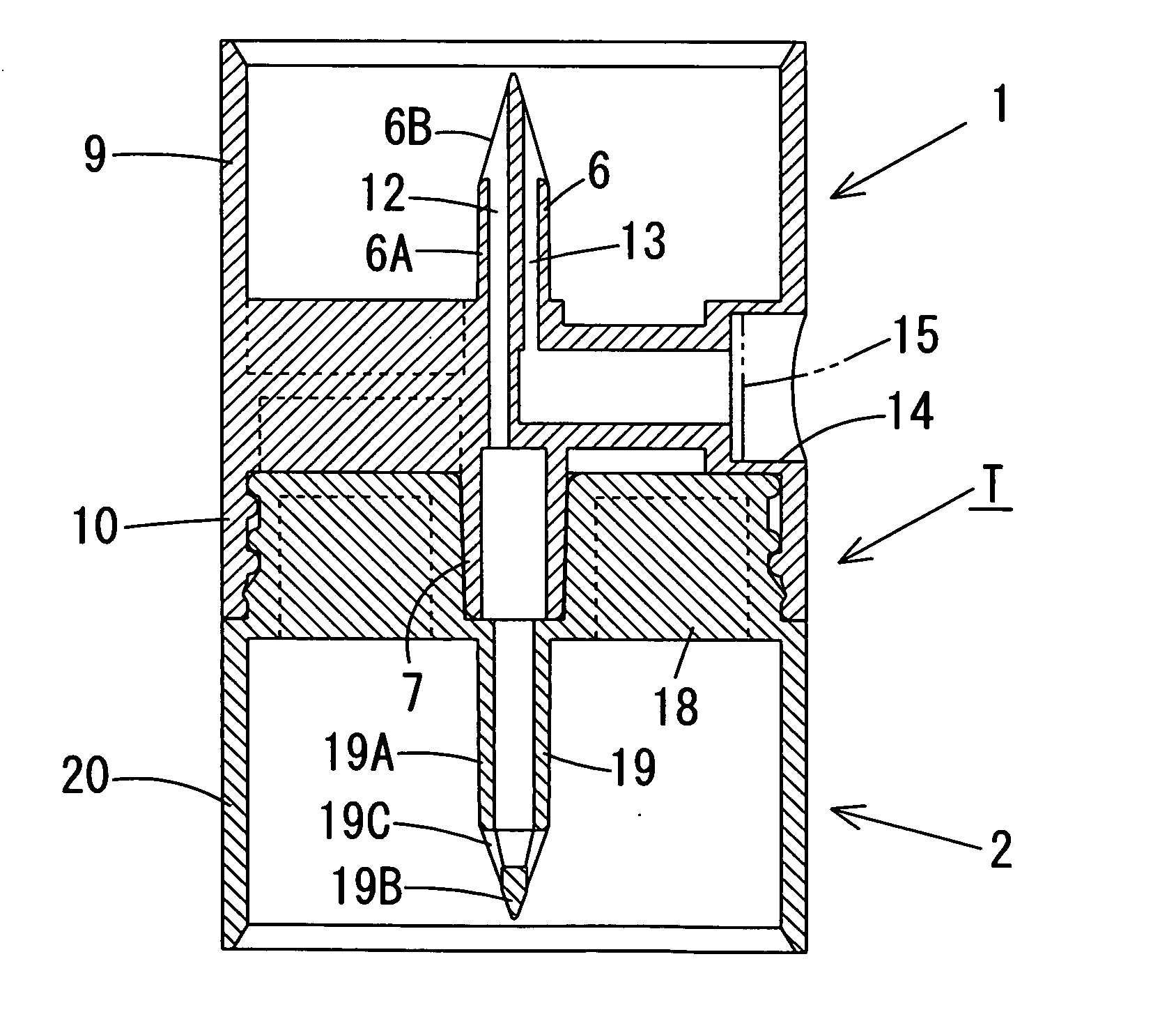
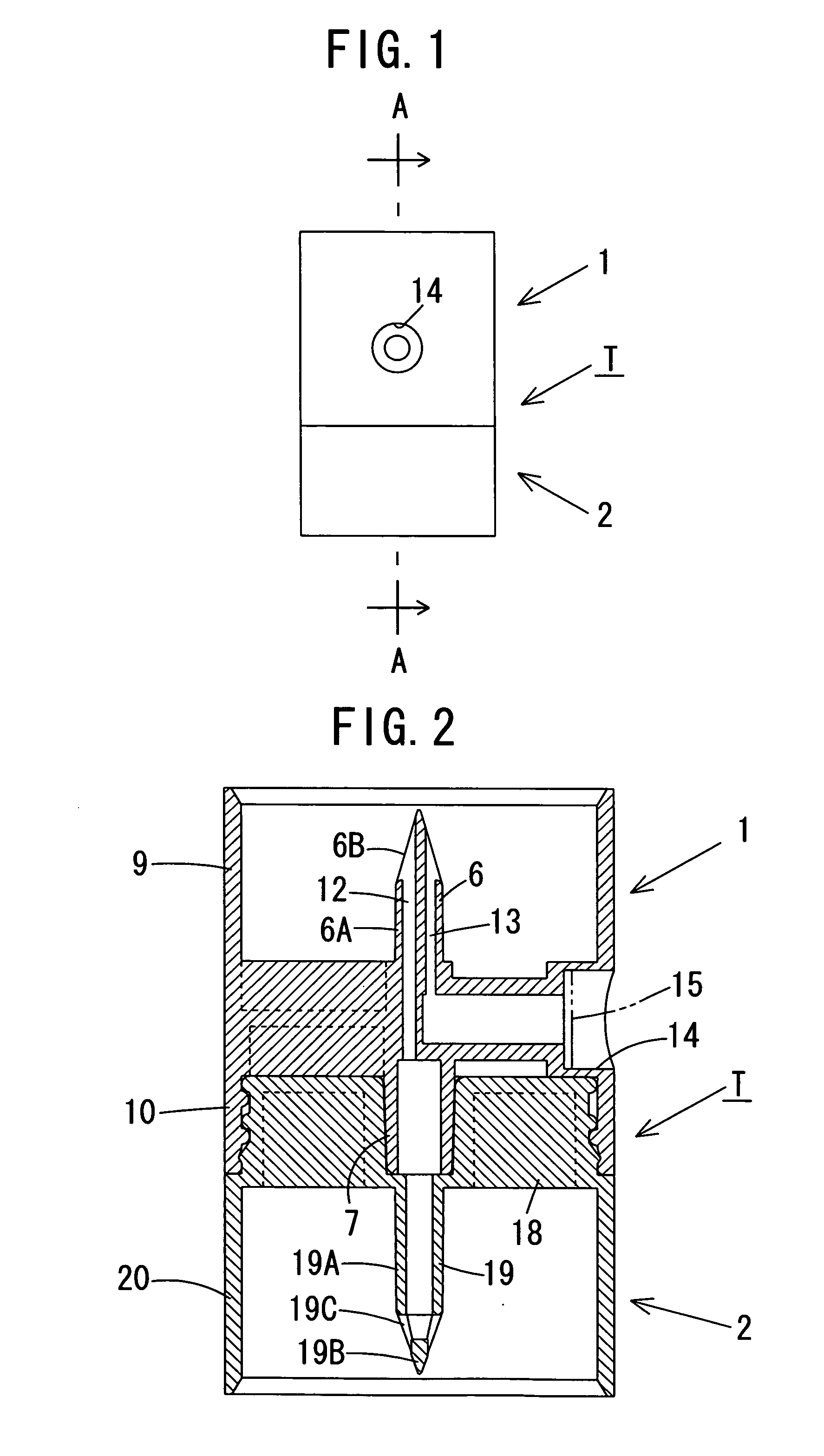
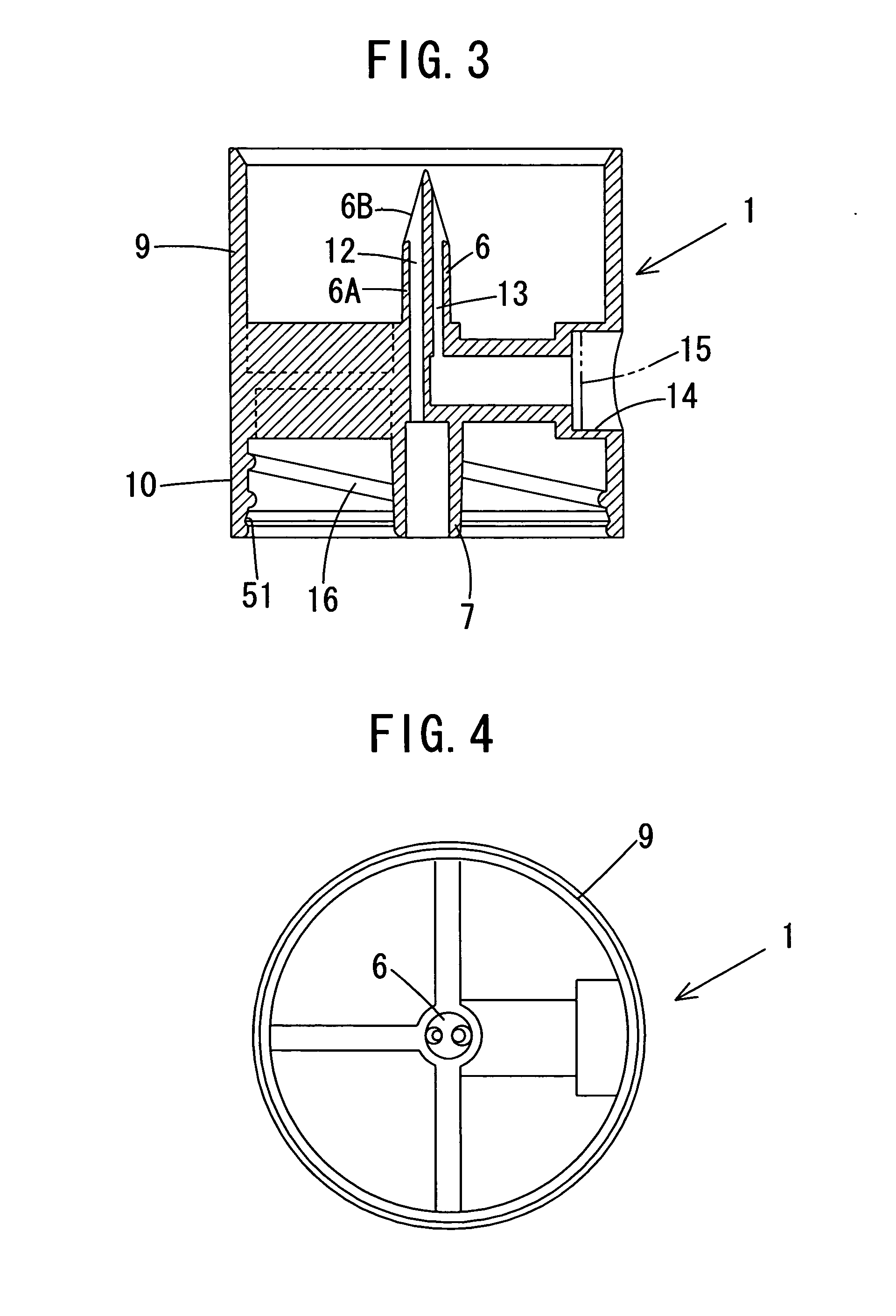
[0100] Referring now to FIG. 1 to FIG. 10, the present invention will be described. As shown in FIG. 1 to FIG. 8, a transfer needle T includes a liquid-specific member 1, and a medicament-specific member 2.
[0101] The liquid-specific member 1 includes a liquid-specific hollow needle 6, a joint portion 7, a skirt 9, and a fitting portion 10, and is integrally formed of hard (or soft) plastic material.
[0102] The liquid-specific hollow needle 6 is disposed in the vertical direction and includes a column-shaped proximal portion 6A, and an upwardly tapered truncated-conical-shaped distal portion 6B. The liquid-specific hollow needle 6 is a two-hole type, and a liquid channel 12 is formed so as to penetrate into the vertical direction in a portion extending from a conical surface to a bottom surface on one side (left side in the drawing), while an air channel 13 opening at the conical surface is formed in the vertical direction on the other side (right side in the drawing) of the liquid-s...
fourth embodiment
[0120]FIG. 17 to FIG. 23 show the present invention. As shown in FIG. 17 to FIG. 19, the fitting portion 10 of the liquid-specific member 1 is formed with the peripheral projection 49 on the outer peripheral surface thereof. The base body 18 of the medicament-specific member 2 is provided with a cylindrical outer fitting portion 50 projecting from an upper end portion of the outer periphery thereof, which is fitted on the fitting portion 10, and the outer fitting portion 50 is formed with the peripheral groove 51 which engages the peripheral projection 49 on an inner peripheral surface thereof.
[0121] Subsequently, a method of molding the transfer needle will be described by taking the liquid-specific member 1 of the fourth embodiment as an example. However, the medicament-specific member 2 of a fourth embodiment, or the liquid-specific member 1 or the medicament-specific member 2 for other embodiments may be molded in the same manner. The liquid-specific member 1 of the forth embodi...
fifth embodiment
[0125]FIG. 24 to FIG. 28 show the present invention, in which the liquid-specific hollow needle 6 and the medicament-specific hollow needle 19 include openings 6C, 19C at the distal (end) portions of the proximal portions 6A, 19A, that is, so called “side hole needle” type. In order to mold the side hole needle, the respective skirts 9, 20 of the liquid-specific member 1 and the medicament-specific member 2 are formed with molding recesses 56, 57.
[0126] According to the embodiment described above, since the liquid-specific hollow needle 6 and the medicament-specific hollow needle 19 include the openings 6C, 19C at the distal (end) portions of the proximal portions 6A, 19A, that is, of so-called “side hole needle” type, when the medicament-specific hollow needle 19 is punctured into the rubber plug of the bial bottle, occurrence of coring may be prevented. Also, when the liquid in the bial bottle is flown into the bial bottle containing the medicament therein via the liquid-specific ...
PUM
| Property | Measurement | Unit |
|---|---|---|
| Flexibility | aaaaa | aaaaa |
Abstract
Description
Claims
Application Information
 - R&D
- Intellectual Property
- Life Sciences
- Materials
- Tech Scout
- Unparalleled Data Quality
- Higher Quality Content
- 60% Fewer Hallucinations
Browse by: Latest US Patents, China's latest patents, Technical Efficacy Thesaurus, Application Domain, Technology Topic, Popular Technical Reports.
© 2025 PatSnap. All rights reserved.Legal|Privacy policy|Modern Slavery Act Transparency Statement|Sitemap|About US| Contact US: help@patsnap.com


