Transfer needle

a technology of transfer needles and needles, which is applied in the field of transfer needles, can solve the problems of difficulty in manufacturing, difficulty in ensuring safety, and difficulty in ensuring safety, and achieves the effects of convenient and reliable dissolving, easy manufacturing, and safe operation

Active Publication Date: 2007-11-13
NIPRO CORP
View PDF47 Cites 92 Cited by
  • Summary
  • Abstract
  • Description
  • Claims
  • Application Information

AI Technical Summary

Benefits of technology

[0016]It is an object of the present invention is to provide a transfer needle that enables safe, easy and reliable dissolving medicament into liquid, such as solvent or drug solution, and preparing drug solution without causing any other problems, and that enables easy manufacturing of metal molds for the transfer needle and molding it.

Problems solved by technology

However, this method is not only complicated, but also associated with a risk of accidental puncture by the metallic hollow needle.
However, in the transfer needle in the related art, there are problems as described below.
That is, the transfer needle is generally formed by injection molding, and thus there arise the following problems.
However, in this method, the length L of the portion to be positioned inside the lower hollow needle 79 plus the insertion portion 84A of the metal mold 84 (this portion is supported to the metal mold 84 only at the lower end) is significantly long, and hence there arises a problem of strength.
In this manner, in the related art, there was a problem in that adjustment a mold clamping force of the metal molds 83, 84 is difficult and hence molding of the transfer needle 77 cannot be performed easily.
Therefore, there was a problem of generation of coring due to twice-puncture of the needle with respect to the rubber plug.
However, in this technology, since the distal ends or the like of the respective hollow needles remain in the respective vials, it is troublesome to dispose the distal (end) portions of the respective hollow needles and the respective vials separately, and in addition, the possibility to cause a needle-puncturing accident by the distal end portions of the respective hollow needles is high, and hence practical application was difficult.

Method used


Image

  • Transfer needle
  • Transfer needle
  • Transfer needle

Examples


first embodiment

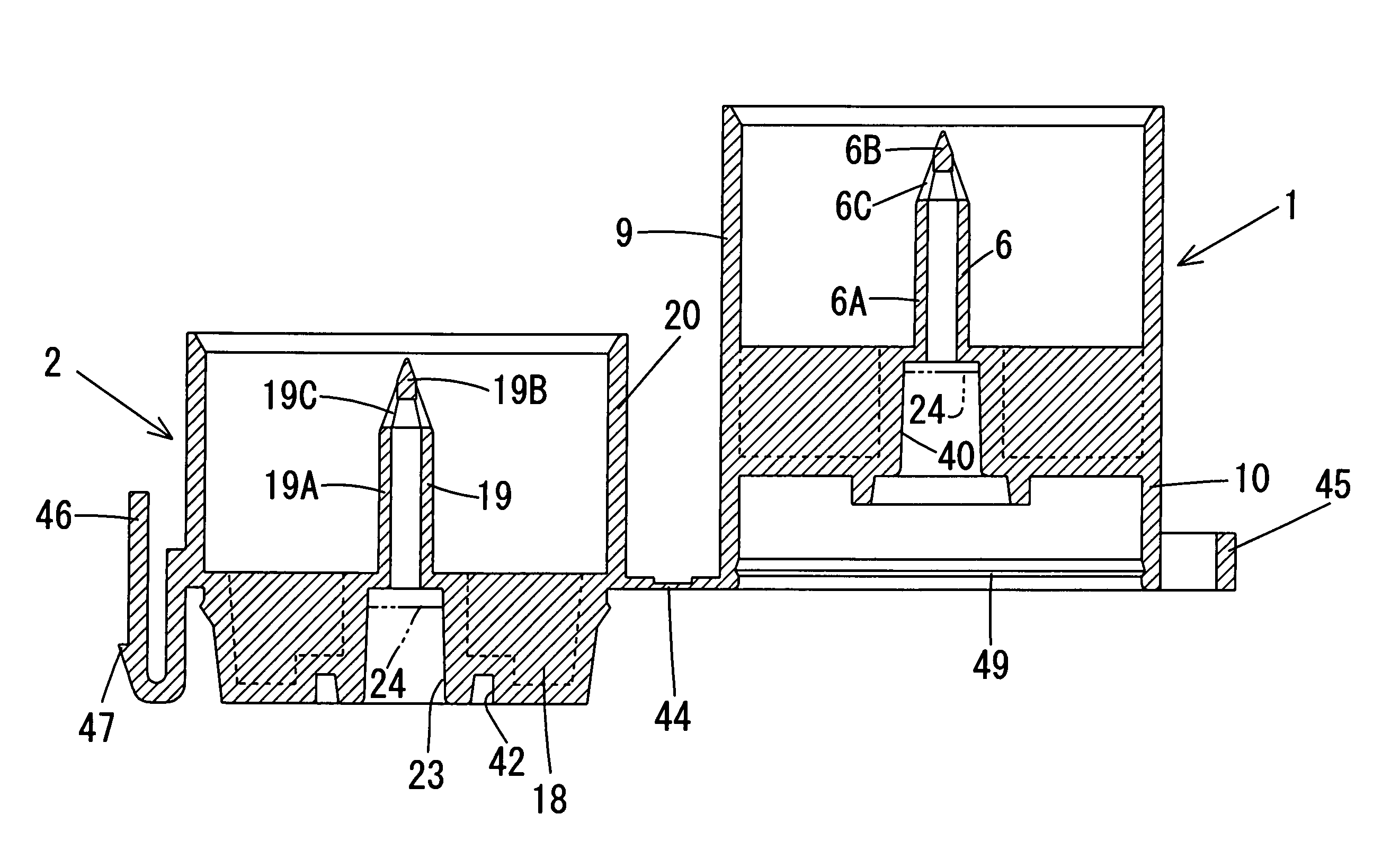
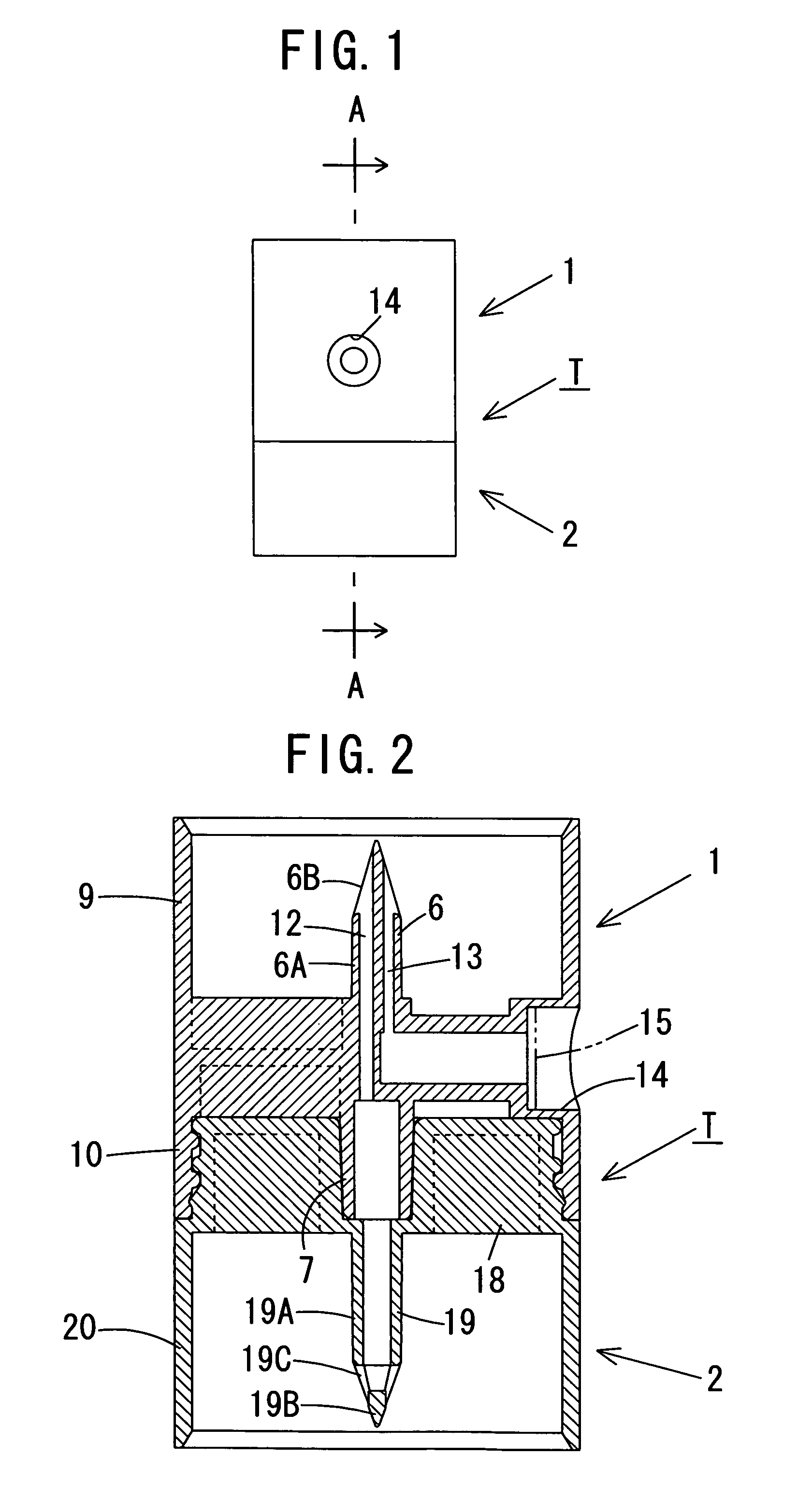
[0101]Referring now to FIG. 1 to FIG. 10, the present invention will be described. As shown in FIG. 1 to FIG. 8, a transfer needle T includes a liquid-specific member 1, and a medicament-specific member 2.

[0102]The liquid-specific member 1 includes a liquid-specific hollow needle 6, a joint portion 7, a skirt 9, and a fitting portion 10, and is integrally formed of hard (or soft) plastic material.

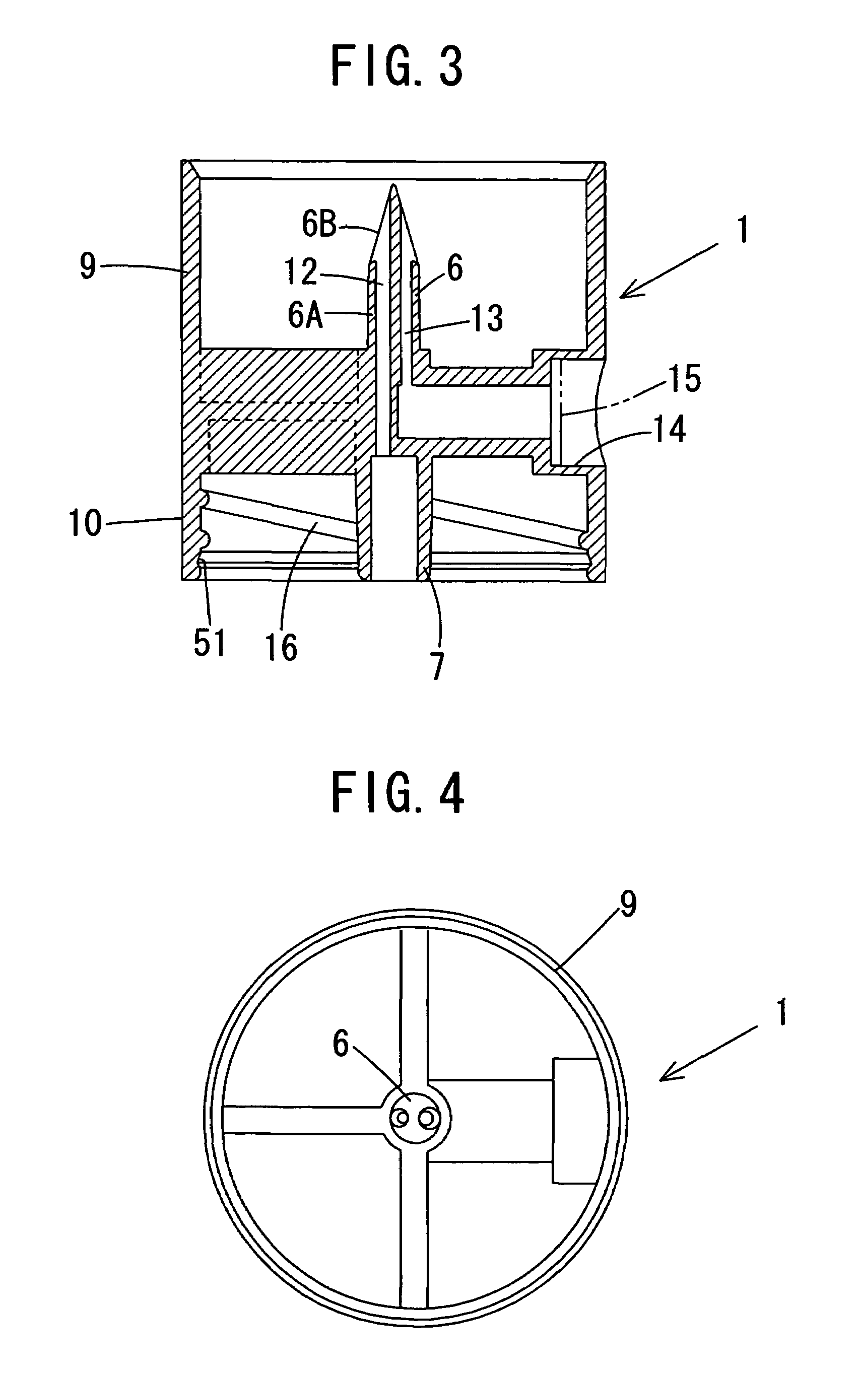
[0103]The liquid-specific hollow needle 6 is disposed in the vertical direction and includes a column-shaped proximal portion 6A, and an upwardly tapered truncated-conical-shaped distal portion 6B. The liquid-specific hollow needle 6 is a two-hole type, and a liquid channel 12 is formed so as to penetrate into the vertical direction in a portion extending from a conical surface to a bottom surface on one side (left side in the drawing), while an air channel 13 opening at the conical surface is formed in the vertical direction on the other side (right side in the drawing) of the liquid-speci...

fourth embodiment

[0121]FIG. 17 to FIG. 23 show the present invention. As shown in FIG. 17 to FIG. 19, the fitting portion 10 of the liquid-specific member 1 is formed with the peripheral projection 49 on the outer peripheral surface thereof. The base body 18 of the medicament-specific member 2 is provided with a cylindrical outer fitting portion 50 projecting from an upper end portion of the outer periphery thereof, which is fitted on the fitting portion 10, and the outer fitting portion 50 is formed with the peripheral groove 51 which engages the peripheral projection 49 on an inner peripheral surface thereof.

[0122]Subsequently, a method of molding the transfer needle will be described by taking the liquid-specific member 1 of the fourth embodiment as an example. However, the medicament-specific member 2 of a fourth embodiment, or the liquid-specific member 1 or the medicament-specific member 2 for other embodiments may be molded in the same manner. The liquid-specific member 1 of the forth embodim...

fifth embodiment

[0126]FIG. 24 to FIG. 28 show the present invention, in which the liquid-specific hollow needle 6 and the medicament-specific hollow needle 19 include openings 6C, 19C at the distal (end) portions of the proximal portions 6A, 19A, that is, so called “side hole needle” type. In order to mold the side hole needle, the respective skirts 9, 20 of the liquid-specific member 1 and the medicament-specific member 2 are formed with molding recesses 56, 57.

[0127]According to the embodiment described above, since the liquid-specific hollow needle 6 and the medicament-specific hollow needle 19 include the openings 6C, 19C at the distal (end) portions of the proximal portions 6A, 19A, that is, of so-called “side hole needle” type, when the medicament-specific hollow needle 19 is punctured into the rubber plug of the vial, occurrence of coring may be prevented. Also, when the liquid in the vial is flown into the vial containing the medicament therein via the liquid-specific hollow needle 6, the j...


PUM

PropertyMeasurementUnit
flexibilityaaaaaaaaaa
metallicaaaaaaaaaa
strengthaaaaaaaaaa

Abstract

A transfer needle comprises: a liquid-specific member; and a medicament-specific member to be separably connected or joined to the liquid-specific member in a liquid-tight state. The liquid-specific member comprises: a liquid-specific hollow needle projecting toward the opposite side from the medicament-specific member. The medicament-specific member comprises: a medicament-specific hollow needle projecting toward the opposite side from the liquid-specific member and communicating with the liquid-specific hollow needle. A female luer is provided on at least one of the liquid-specific member and the medicament-specific member at a position opposing to the other. The female luer communicates with the one hollow needle and is separably connected with an injection needle connecting portion of a syringe in a liquid-tight state.

Description

[0001]The present application claims priority to Japanese Application No. 2003-275735 filed Jul. 17, 2003.BACKGROUND OF THE INVENTION[0002]1. Field of the Invention[0003]The present invention relates to a transfer needle and, more specifically, to a transfer needle that enables safe, easy and reliable injection of liquid such as solvent or drug solution from its own container into a container with medicament contained therein, when dissolving the medicament in liquid such as solvent or drug solution and preparing drug solution for preparing fluid infusion and the like.[0004]2. Description of the Related Art[0005]Medicaments which are chemically unstable and may change their natures in a state of fluid infusion, such as antibiotics, anticancer agent, or blood preparation, are normally stored in a vial sealed with a rubber plug in a freeze-dried state, and then those medicaments are dissolved in a solvent such as distilled water, physiological salt solution, or glucose liquid and drug...

Claims


Application Information

Patent Timeline
Patent Type & Authority Patents(United States)
IPC IPC(8): A61B19/00A61M39/20A61J3/00A61J1/00A61J1/20A61M39/02B29C45/26B29C65/58
CPCA61J1/2089A61J1/2096B29L2031/759B29L2031/753B29C66/5221A61J2001/201A61J2001/2013A61J2001/2072A61J2001/2075A61J2001/2082B29C45/2628B29C65/58B29C66/1142B29C65/00A61J1/201A61J1/2075A61J1/2072A61J1/2082A61J1/2013
Inventor KUBO, TOMOHIKOHASEGAWA, SHUJISUNAGA, YOSHIYUKIKINOSHITA, TAKAO
Owner NIPRO CORP
Why Eureka
Try Eureka