Metallic implantable grafts and method of making same

a technology of implantable grafts and metals, which is applied in the field of implantable metallic medical devices, can solve the problems of short-term platelet activity and/or thrombosis of metals, metals are also susceptible to short-term platelet activity and/or thrombosis, and materials commonly used as medical grafts, such as polymers, to achieve the effect of facilitating transmural endothelialization, imparting pliability and/or elasti

Active Publication Date: 2005-02-10
VACTRONIX SCI LLC
View PDF26 Cites 57 Cited by
  • Summary
  • Abstract
  • Description
  • Claims
  • Application Information

AI Technical Summary

Benefits of technology

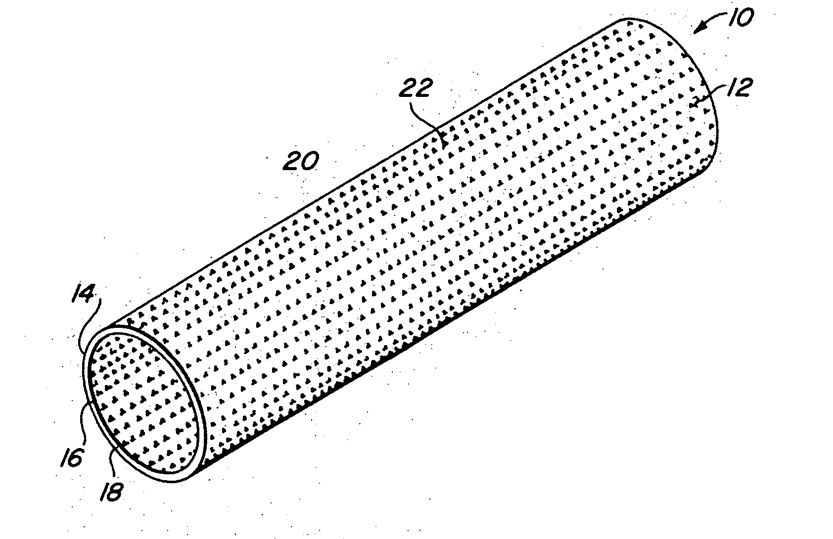
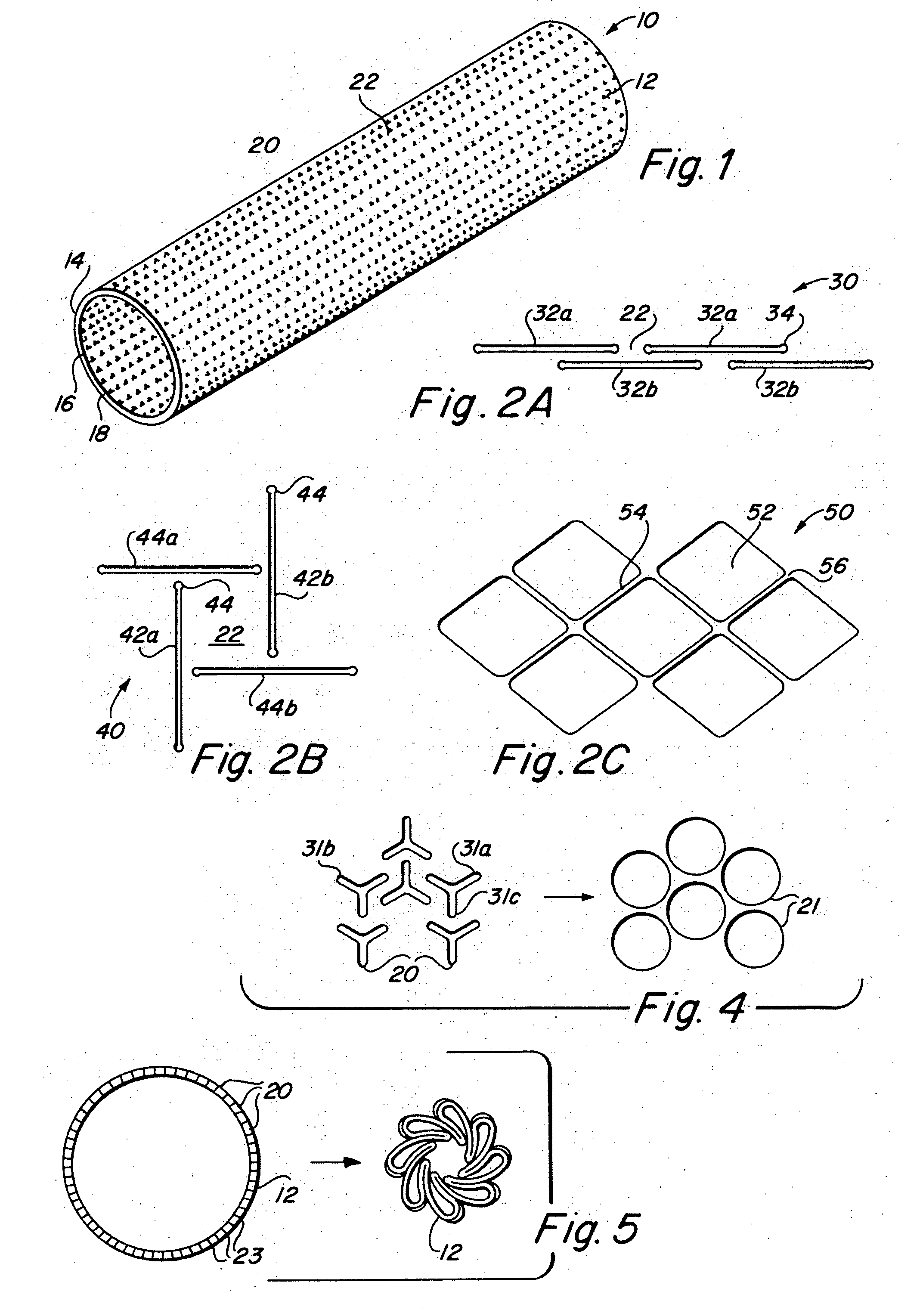
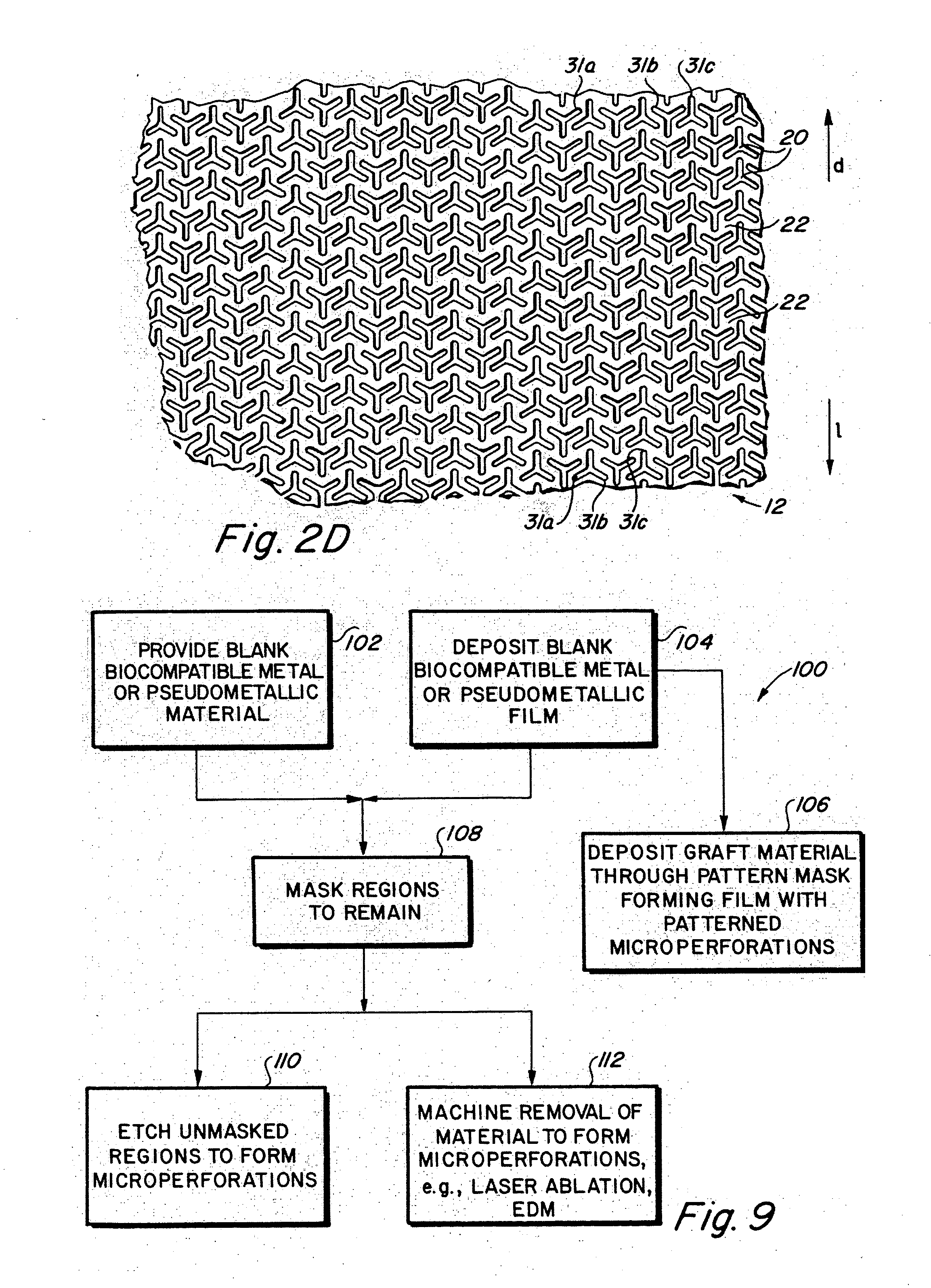
[0015] In accordance with a preferred embodiment of the invention, there is provided a self-supporting graft member having a plurality of pleats or corrugations in wall surfaces thereof and may have a plurality of microperforations passing through the wall thickness of the graft. While the inventive graft member may assume virtually any geometric configuration, including sheets, tubes or rings, preferred geometries for the graft member are generally planar and generally tubular. Where present, the plurality of microperforations serve to impart geometric compliance to the graft, geometric distendability to the graft and / or limit or permit the passage of body fluids or biological matter through the graft, such as facilitating transmural endothelialization while preventing fluid flow through the wall of the graft under normal physiological conditions. The plurality of microperforations may also impart a fabric-like quality to the graft by imparting pliability and / or elastic, plastic or superelastic compliance to the graft, such as that required for longitudinal flexibility in the case of a vascular graft.
[0016] In a first embodiment, the graft may be made from plastically deformable materials such that upon application of a force, the microperforations geometrically deform to impart permanent enlargement of one or more axes of the graft, such as length in the case of a planar graft, e.g., a surgical patch graft, or diameter, such as in the case of a tubular graft, e.g., a vascular graft. In a second embodiment, the graft may be fabricated of elastic or superelastic materials. Elastic and / or superelastic materials will permit the microperforations to geometrically deform under an applied force in a manner that allows for a recoverable change in one or more axes of the graft.

Problems solved by technology

Because of their relatively greater adhesive surface profiles, metals are also susceptible to short-term platelet activity and / or thrombogenicity.
It is known that materials commonly used as medical grafts, such as polymers, do not become covered with EC and therefore do not heal after they are placed in the arteries.
However, these approaches fail to remedy the lack of clinically acceptable endothelialization of polymer grafts.
Specifically, vacuum deposition is an additive technique that lends itself toward fabrication of substantially uniformly thin materials with potentially complex three dimensional geometries and structures that cannot be cost-effectively achieved, or in some cases achieved at all, by employing conventional wrought fabrication techniques.
All of these processing steps have disadvantages including contamination, material property degradation, ultimate achievable configurations, dimensions and tolerances, biocompatibility and cost.
For example conventional wrought processes are not suitable for fabricating tubes having diameters greater than about 20 mm diameter, nor are such processes suitable for fabricating materials having wall thicknesses down to about 5 μm with sub-μm tolerances.

Method used


Image

  • Metallic implantable grafts and method of making same
  • Metallic implantable grafts and method of making same
  • Metallic implantable grafts and method of making same

Examples


example

[0069] A 5 μm thick NiTi graft having a pattern of microperforations consisting of parallel staggered longitudinally oriented linear slots, each slot being 430 μm length, 25 μm width, and having 50 μm diameter fillets on each end of each linear slot, was mounted onto a 6 mm NiTi stent and delivered endoluminally to the left carotid artery of a swine. After 28 days, the swine was euthanized, and the graft explanted from the left carotid artery. Samples were prepared using standard hematoxylin and eosin staining procedures, and microscope slides prepared. As illustrated in FIGS. 10A histology of the explanted samples revealed complete endothelialization around the graft 12, negligible neointimal proliferation with the absence of trauma to the internal elastic lamina. FIG. 10B is a sample indicating cross-talk between the arterial superficial and deep layers with the transmural formation of small capillaries.

[0070] Alternate embodiments of the inventive graft are depicted in FIGS. 11-...


PUM

PropertyMeasurementUnit
thicknessaaaaaaaaaa
thicknessaaaaaaaaaa
diameteraaaaaaaaaa

Abstract

Implantable medical grafts fabricated of metallic or pseudometallic films of biocompatible materials having a plurality of microperforations passing through the film in a pattern that imparts fabric-like qualities to the graft or permits the geometric deformation of the graft. The implantable graft is preferably fabricated by vacuum deposition of metallic and / or pseudometallic materials into either single or multi-layered structures with the plurality of microperforations either being formed during deposition or after deposition by selective removal of sections of the deposited film. The implantable medical grafts are suitable for use as endoluminal or surgical grafts and may be used as vascular grafts, stent-grafts, skin grafts, shunts, bone grafts, surgical patches, non-vascular conduits, valvular leaflets, filters, occlusion membranes, artificial sphincters, tendons and ligaments.

Description

CROSS REFERENCE TO RELATED APPLICATIONS [0001] The present application claims priority to provisional application, U.S. Ser. No. 60 / 468,425, filed May 7, 2003 and is related to commonly assigned, co-pending U.S. applications Ser. No. 10 / 135,136 filed Apr. 29, 2002, which claims priority from U.S. Ser. No. 60 / 310,617, filed Aug. 7, 2001, U.S. Ser. No. 09 / 7455,304, filed Dec. 22, 2000 which is a divisional of Ser. No. 09 / 443,929, filed Nov. 19, 1999, now U.S. Pat. No. 6,379,383, and U.S. Ser. Nos. 10 / 289,974 and 10 / 289,843 09 / 532,164 both filed Nov. 6, 2002 which are continuation applications of U.S. Ser. No. 09 / 532,164, filed Mar. 20, 2000, now U.S. Pat. No. 6,537,310.BACKGROUND OF THE INVENTION [0002] The present invention relates generally to implantable metallic medical devices. More specifically, the present invention relates to implantable medical devices, including, for example, surgical and endoluminal vascular grafts, stent grafts, covered stents, skin grafts, shunts, bone gr...

Claims


Application Information

Patent Timeline
Patent Type & Authority Applications(United States)
IPC IPC(8): A61FA61F2/06A61F2/82C23C14/00
CPCA61F2/06A61F2/82A61L27/50A61F2/04A61L31/14C23C14/0005A61L31/022Y10T83/04A61L27/06
Inventor BANAS, CHRISTOPHER E.PALMAZ, JULIO C.
Owner VACTRONIX SCI LLC
Why Eureka
Try Eureka