Pipe burying method

Inactive Publication Date: 2005-02-17
KOMATSU LTD
View PDF6 Cites 23 Cited by
  • Summary
  • Abstract
  • Description
  • Claims
  • Application Information

AI Technical Summary

Benefits of technology

[0019] According to the pipe burying method of the third aspect, since various types of reamer 6 can be formed by changing the platy member 9 to be attached to the reamer main body 8, it is possible to simply form the reamer 6 that is suited to the soil type

Problems solved by technology

In addition, since the sandy soil has a large falling property, it is necessary to make a blade height of the drilling blade small (in this case, if the height of the drilling blade is made low, an amount of drilling is made small).
In addition, in the sof

Method used


Image

  • Pipe burying method
  • Pipe burying method
  • Pipe burying method

Examples


Example

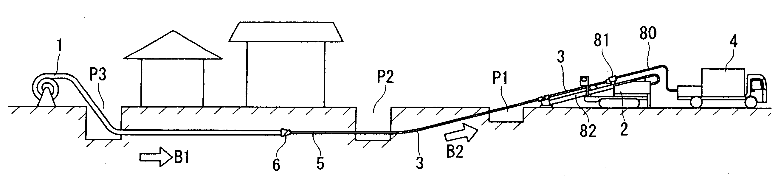
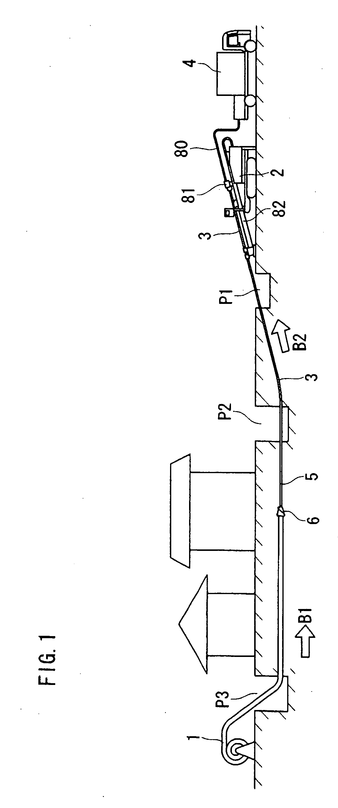
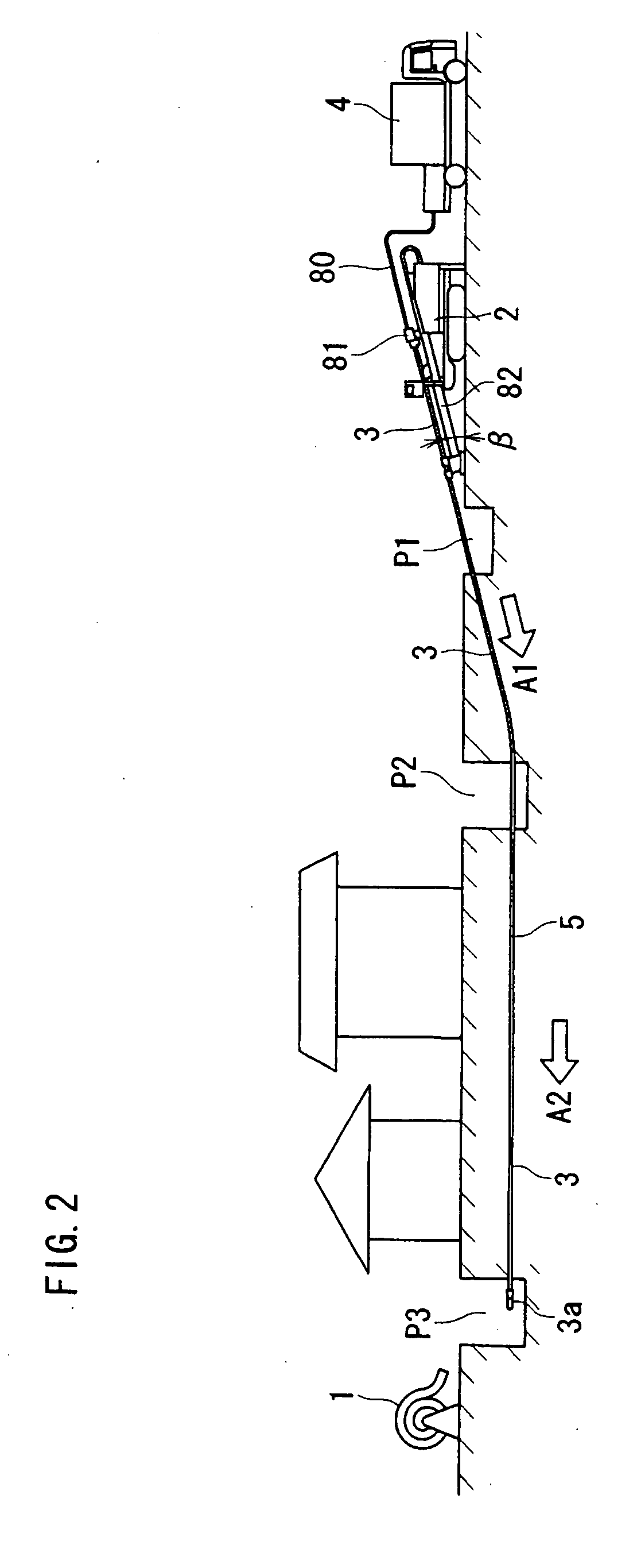
[0032] In the following, with reference to the drawings, embodiments of the pipe burying method according to the present invention will be described in detail below. In this pipe burying method, the above-described horizontal drill construction is employed and a ground boring machine shown in FIGS. 1 and 2 is used. According to the pipe burying method, at first, a pilot hole 5 as shown in FIG. 2 is formed. This pilot hole 5 is formed by the above-described operation shown in FIG. 10 and this operation will be briefly described below with reference to FIG. 1. At first, as shown in FIG. 2, a penetration pit P1, a starting pit P2, and an attainment pit P3 are formed on the earth at certain intervals each other. Then, on a drill driving device 2, a rod (a hollow rod) 3 with a leading body (a pilot head) 3a fit at its front end is installed to be supported. Then, while emitting the drilling fluid (a crystal water, a muddy water, and a bentonite muddy water or the like) that is pressure-f...


PUM


Abstract

The invention provides a pipe burying method by which a diameter of a pilot hole can be efficiently and reliably enlarged depending on various types of soil and a burying operation of a buried pipe is made stable. The method involves preparing various types of platy members, selecting a platy member suitable for a soil type from among the various types of platy members on the basis of a soil type search of a burying place, and attaching the selected platy member to a reamer main body, thereby forming a reamer suitable for the soil type. The method further involves annexing this reamer at a front end of a rod in a pilot hole, and pulling out this rod from the pilot hole while rotating the reamer together with the rotation of the rod, thereby burying a buried pipe to be connected to the reamer in the earth.

Description

BACKGROUND OF THE INVENTION [0001] 1. Field of the Invention [0002] The present invention relates to a pipe burying method for burying a pipe such as a water pipe, a gas pipe, a drain pipe, a sheath pipe for a signal cable, and a fiber cable or the like (hereinafter, referred to as “a buried pipe”) in the earth. [0003] 2. Description of the Related Art [0004] A pipe burying method for burying a pipe such as a water pipe, a gas pipe, a drain pipe, a sheath pipe for a signal cable, and a fiber cable or the like (hereinafter, referred to as “a buried pipe”) in the earth is roughly divided into a drive construction method for driving the earth and burying a pipe, and a non-drive construction method for burying a pipe without driving the earth. The both construction methods have an advantage and a disadvantage, respectively. In other words, as compared to the drive construction method, the non-drive construction method has an economical advantage such that a pipe can be easily buried as ...

Claims


Application Information

Patent Timeline
IPC IPC(8): E21D9/06E21B7/20E21B7/28E21B10/26E21B17/05F16L1/024
CPCE21B7/20E21B17/05E21B10/26E21B7/28
Inventor YOUAN, TOYOHIKO
Owner KOMATSU LTD
Why Eureka
Try Eureka