Varying refractive index optical medium using at least two materials with thicknesses less than a wavelength

a technology of refractive index and optical medium, which is applied in the direction of instruments, cladded optical fibres, lenses, etc., can solve the problems of strong absorption of light in the standard communication wavelength band, low light focusing power of the lens, and limited application methods, etc., and achieve different refractive indices and high maximum refractive index changes.

Active Publication Date: 2005-02-17
HO SENG TIONG
View PDF69 Cites 24 Cited by
  • Summary
  • Abstract
  • Description
  • Claims
  • Application Information

AI Technical Summary

Benefits of technology

Embodiments of the present invention provide a device having a graded (or distributed or gradient) effective refractive index profile with a very high maximum refractive index change. According to one aspect of the present invention a light transmitting device with a graded index of refraction includes alternating layers of two (or more) materials having significantly different refractive indices (e.g., a difference of at least 0.2). The thickness of the layers of at least one of the materials is substantially less than the effective light wavelength of interest. The effective index of refraction in a local region within the device depends on the ratio of the average volumes of the two materials in the local region; because the relative thicknesses of the layers can be made different for different layers, a graded index of refraction can be provided. Control of the layer thicknesses also allows an arbitrary refractive index profile to be provided.

Problems solved by technology

As a result, when such a method is used to make a graded refractive index lens to focus a light beam, the light focusing power of the lens is generally low.
This method has limited application because the gradient is not permanent, and the maximum index change is only about 0.02.
The disadvantages associated with plastics include the relatively strong absorption of light in the standard communication wavelength band, as well as the relatively low thermal and lifetime stability of the plastic material.
However, most glasses that are well accepted for optical communication do not possess the required uniform phase separation property.
One problem with this technique is that cracking of the film tends to occur as the film grows thicker and the amount of dopant in the solution increases.
It is thus difficult to produce a film thickness of the order of about 10 μm.
None of these methods is able to produce a maximum index change greater than about 0.2.
In addition, none of these methods is able to produce an arbitrary refractive index profile with high precision because these methods generally rely in some way on diffusion of one material into another, which cannot be precisely controlled.

Method used


Image

  • Varying refractive index optical medium using at least two materials with thicknesses less than a wavelength
  • Varying refractive index optical medium using at least two materials with thicknesses less than a wavelength
  • Varying refractive index optical medium using at least two materials with thicknesses less than a wavelength

Examples


Embodiment Construction

As is generally known, light is an electromagnetic wave oscillating at high frequency. All portions of the electromagnetic spectrum are meant to be included, including but not limited to, radiowaves, microwaves, millimeter waves, infrared radiation, visible light, and ultraviolet radiation. When light travels through a dielectric medium (e.g., glass), its speed (v) is reduced relative to the speed of light in vacuum (c). The refractive index (n) of the medium is defined as n=c / v. The frequency of the light is unchanged, and the wavelength is reduced from λo in vacuum to λeff=λo / n in the medium.

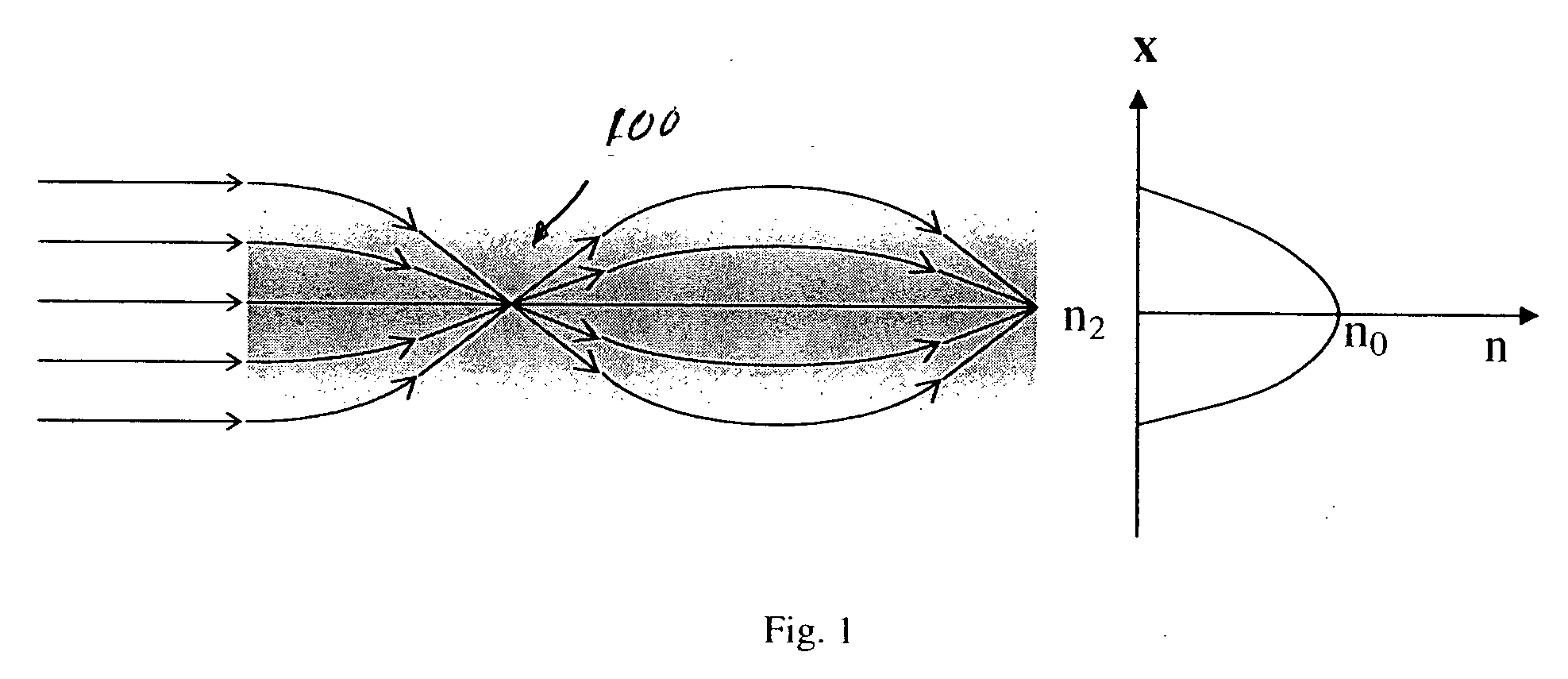
As shown in FIG. 1, in a graded refractive index (“GRIN”) optical medium 100, the material has a refractive index n(r) that decreases substantially continuously from a value of no at the central axis (r=0) to a value of nb at the outside border (r=a). In this example, n(r) has a parabolic refractive index distribution given by the formula: n⁡(r)=no⁡[1-Δ⁡(ra)2],where⁢ ⁢Δ=n0-nbn0.

This index...


PUM


Abstract

An optical medium has a graded effective refractive index with a high maximum refractive index change. The medium is formed using alternating layers of two or more materials having significantly different refractive indices. The thickness of the layers of at least one of the materials is substantially less than the effective light wavelength of interest. The effective index of refraction in a local region within the medium depends on the ratio of the average volumes of the two materials in the local region. A graded index of refraction is provided by varying the relative thicknesses of the two materials.

Description

BACKGROUND OF THE INVENTION The present invention relates generally to structures having a refractive index distribution and in particular to an optical medium having an arbitrary desired effective refractive index distribution using at least two materials with thicknesses less than a wavelength. Optical communication systems require optical components to guide and / or manipulate a light beam in continuous or pulse format. Of the various optical components used in optical communication systems, some have a continuous change in the distribution of the refractive index. Examples include graded refractive index multimode optical fibers [e.g., Cohen et al., “Multimode Optical Fiber,” U.S. Pat. No. 3,989,350, Nov. 2, 1976; Fleming, Jr., “Multimode Optical Fiber,” U.S. Pat. No. 4,033,667, Jul. 5, 1977 and graded refractive index rod lenses [e.g., Ho Shang Lee, “Miniaturization of Gradient Index Lens Used in Optical Components,” U.S. Pat. No. 6,088,166, Jul. 11, 2000]. A continuous refrac...

Claims


Application Information

Patent Timeline
Patent Type & Authority Applications(United States)
IPC IPC(8): G02B6/32
CPCG02B6/32
Inventor ZHOU, YANHO, SENG-TIONG
Owner HO SENG TIONG
Why Eureka
Try Eureka