Pressure independent control valve

a control valve and pressure independent technology, applied in the direction of fluid pressure control, process and machine control, instruments, etc., can solve the problems of large control surface, net force that moves the diaphragm, and unbalance between the two forces

Inactive Publication Date: 2005-02-24
CARLSON BENGT A
View PDF12 Cites 38 Cited by
  • Summary
  • Abstract
  • Description
  • Claims
  • Application Information

AI Technical Summary

Benefits of technology

Calculation of the influence of the incoming pressure P1 on the outgoing pressure P2, at different effective areas. P3 atmospheric pressure.

Problems solved by technology

Pressure variations causes unbalance between the two forces and produces a net force that moves the diaphragm.
When a large flow capacity is needed, the control surface must be large, and the force counteracting the spring is quite large.
The drawback is that the movement changes the spring tension, which also changes the set-point.
However, this increases the size and cost of the APCV.
This of course means that also the housing surrounding the diaphragm need to be quite large and costly.
However, many of these valves (sleeve type, for example) tend to leak, so the very small flows can not be controlled.
However, this an added complication which increases the cost.
The problem is that the flow not only depends upon how much the valves are open, but also upon the differential pressure across the valve.
A sudden pressure variation in the piping system changes the flow through a control valve and the control is upset.
Pressure variations due to load changes distorts the flow characteristics of the control valves, which is detrimental for stable control.
It is very difficult to correctly size control valves.
Unfortunately, it is very difficult to obtain a correct information about the differential pressure that reflects the actual conditions.
Without correct information, the control valves will not be sized correctly.
Undersized control valves can not supply the needed flow and must be replaced.
However, it is very detrimental for stable control, especially at low loads.
The problem so far has been the high cost.
It is primarily the ADPCV that increases the cost.

Method used


Image

  • Pressure independent control valve
  • Pressure independent control valve
  • Pressure independent control valve

Examples


example 1

; A=10 sq.in B=10 sq.in S=100 lb When P1=10 psig P2=((100 −10(10−10)) / 10=10 psig When P1=100 psig P2=((100 −100(10−10)) / 10=10 psig There is no change in P2 when P1 is increased from 10 to 100 psig.

example 2

; A=9 sq.in B=10 sq.in S=100 lb When P1=10 psig P2=((100−10(10−9)) / 9=10 psig When P1=100 psig P2=((100−100(10−9)) / 9=0 psig

P2 changes from 10 psig to 0 psig when P1 increases from 10 psi to 100 psig. It is obvious that it is important that the effective areas of the diaphragm and the disk are the same. Otherwise the accuracy is compromised.

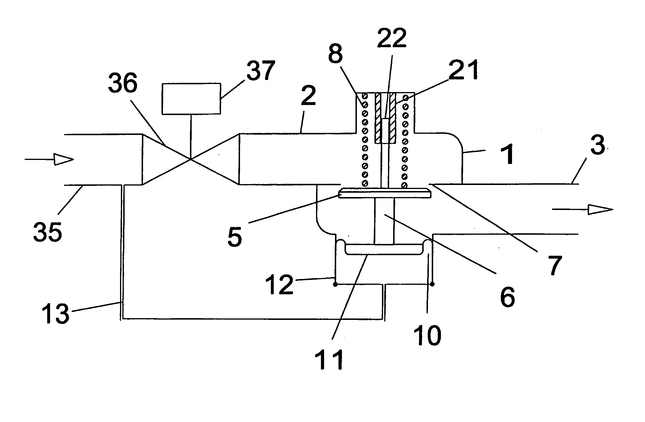
See FIG. 9. It is a back pressure APCV and controls the inlet pressure (P1). The control disk (5) is located above the seat (7). The flow direction is reversed compared to FIG. 1-8. The (upstream) inlet pressure (P1) acts upon the control disk (5) and together with the spring produces an upward force, which is balanced by the force produced by the (higher) pressure (P3) above the diaphragm (10). If instead, the pressure above the diaphragm is lower than the inlet pressure, the spring then is located above the diaphragm and pushes down. The lower part of the control disk (5) has an optional guide pin (22), which slides inside a guide bushing (...


PUM


Abstract

Simple APCV, ADPCV and PICV's are provided. The APCV's are referenced to the atmosphere and control the gauge pressure, either upstream or downstream. The ADPCV's are the same as the APCV's, differing in that they are not referenced to the atmosphere. They are instead referenced to a second point in the fluid flow system and control the differential pressure. The PICV's are control valves connected in series with ADPCV's and control the fluid flow rate through the valve independently of variations in the line pressure. A preferred APCV has a valve body (1) with connections for a single-phase fluid line and a flow passage between the inlet (2) and the outlet (3) of said fluid line, with an opening having a defined seat office (7) intersecting the flow passage. A moveable assembly, comprising a disk (5) or cup is connected to a pressure sensing member (4), having essentially the same effective surface area. The moveable assembly, is biased by a force, and is free to automatically move to any intermediate position between fully open and closed, producing a desired outlet pressure which minus the reference pressure, times the effective surface area of the disk or cup generates an opposing force equal to the biasing force.

Description

FIELD OF THE INVENTION This invention refers to provisional patent application #60 / 149,399 File date Aug. 17, 1999. The invention is an automatic pressure control valve which can be used for pressure control of a liquid or gas media flow. It can be used to control the gauge pressure, or the differential pressure between two points in a system. It can control the pressure in for example; compressed air, water or steam lines, oil and fuel supplies and air handling systems. It can also be used to control the liquid level in tanks. An important application is together with control valves, for automatic flow rate control. The automatic pressure control valve is piped in series with the control valve and arranged so it maintains a constant differential pressure across the control valve. The two valves works together as a pressure independent control valve. DESCRIPTION OF PRIOR ART Automatic pressure control valves are used to control liquid or gas media flow so the pressure is essent...

Claims


Application Information

Patent Timeline
Patent Type & Authority Applications(United States)
IPC IPC(8): G05D7/01G05D16/06
CPCG05D16/0655G05D7/0106Y10T137/7781
Inventor CARLSON, BENGT A.
Owner CARLSON BENGT A
Why Eureka
Try Eureka