Induction heat treatment method and coil and article treated thereby

Inactive Publication Date: 2005-02-24
FORD MOTOR CO
View PDF22 Cites 17 Cited by
  • Summary
  • Abstract
  • Description
  • Claims
  • Application Information

AI Technical Summary

Benefits of technology

[0011] The present invention undertakes to improve the production of such components as compared to previous methods, such as carburizing, by enabling the use of induction hardening, and thereby providing better control over the process by hardening one component at a time, improving the metallurgical and mechanical properties of the components, and allowing for a reduction in heat treatment cost.
[0012] The hardening operation will be simplified, and allow improved control, by the application of this invention because the components will be processed one at a time. The integration of the part location, heating, and quenching functions into a single, robust machine simplifies the heat treatment operation compared to previous methods by reducing the part handling requirements and reducing complex cycle parameters (e.g. adjusting the entire process for part-to-part variations in a batch of parts due to different temperature and environmental conditions that exist in a large heat treating furnace) to a small set of

Problems solved by technology

However, induction hardening has significant limitations in cases where the surface requiring heat treatment is irregular, such as gears having relatively larger teeth where the distance from the tip to the root of a tooth is such that the electromagnetic coupling, and hence induction heating, varies significantly from the tip to the root.
While some solutions have been proposed to facilitate the use of induction hardening with articles having irregular surfaces, such as the use of different coils and different induction frequencies to treat different portions of the surface, or the use of coil designs that are adapted to the contour of the irregularities in order to provide more uniform inductive coupling, induction hardening has not been used for various types of components, such

Method used


Image

  • Induction heat treatment method and coil and article treated thereby
  • Induction heat treatment method and coil and article treated thereby
  • Induction heat treatment method and coil and article treated thereby

Examples


Embodiment Construction

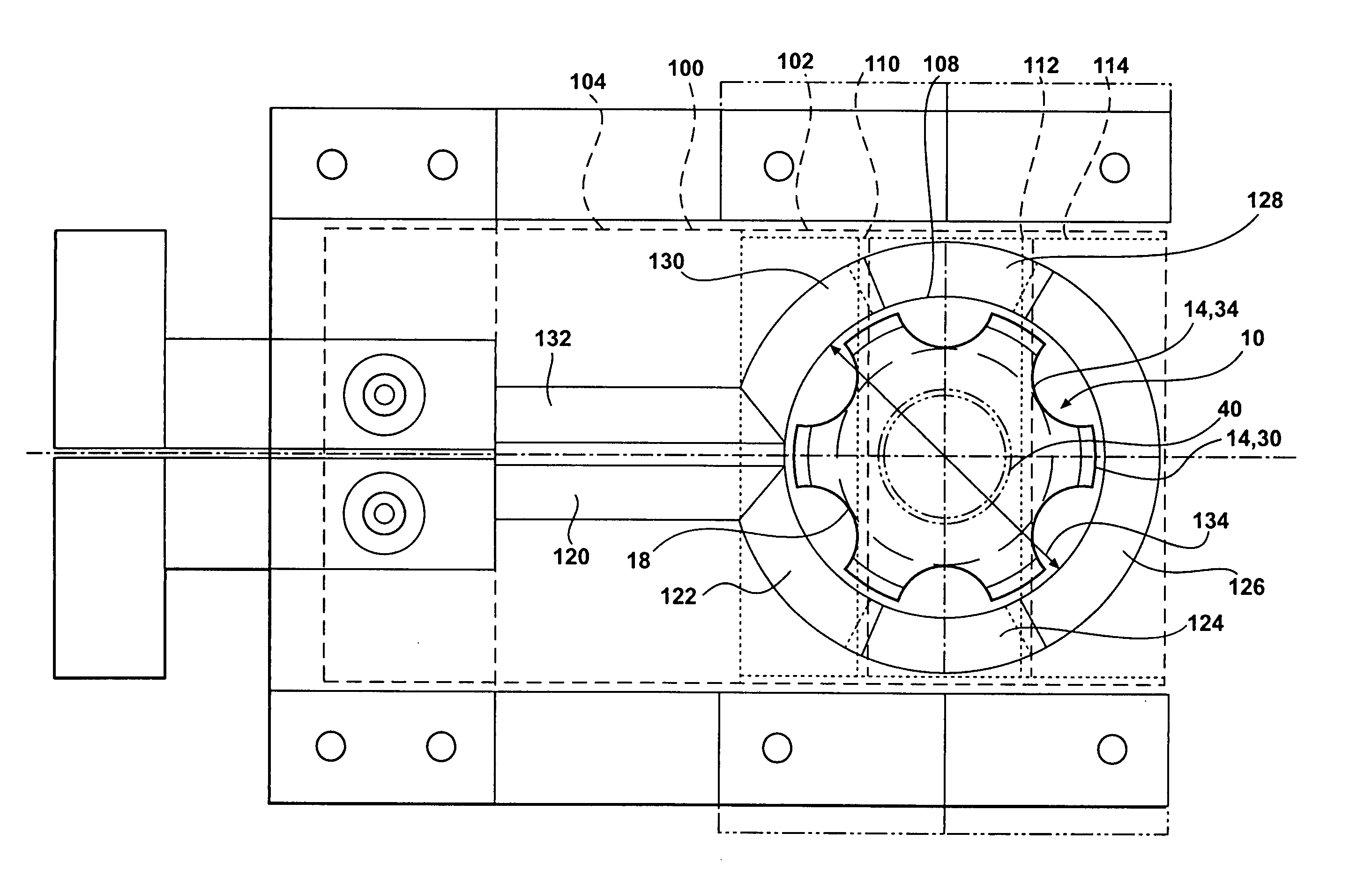
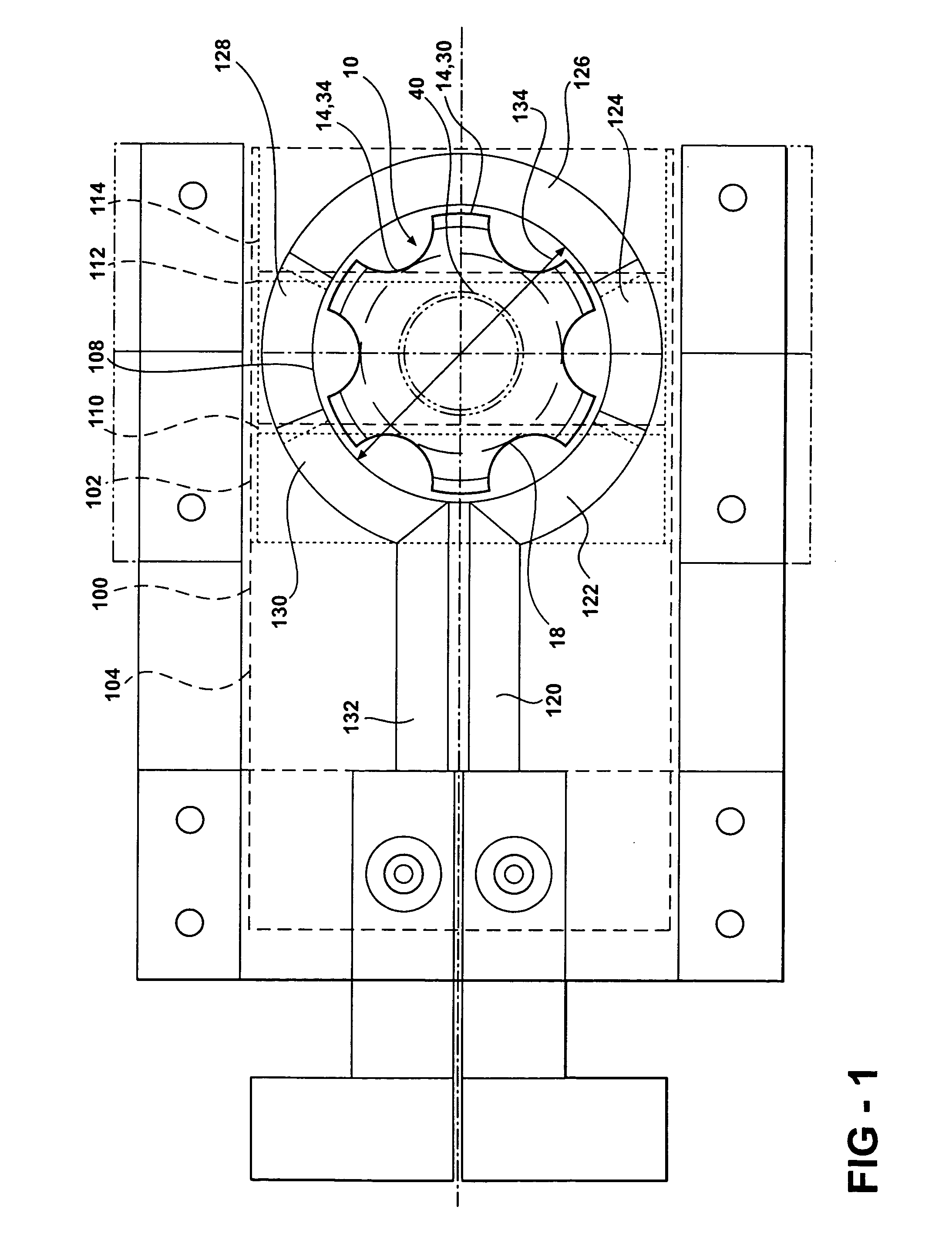
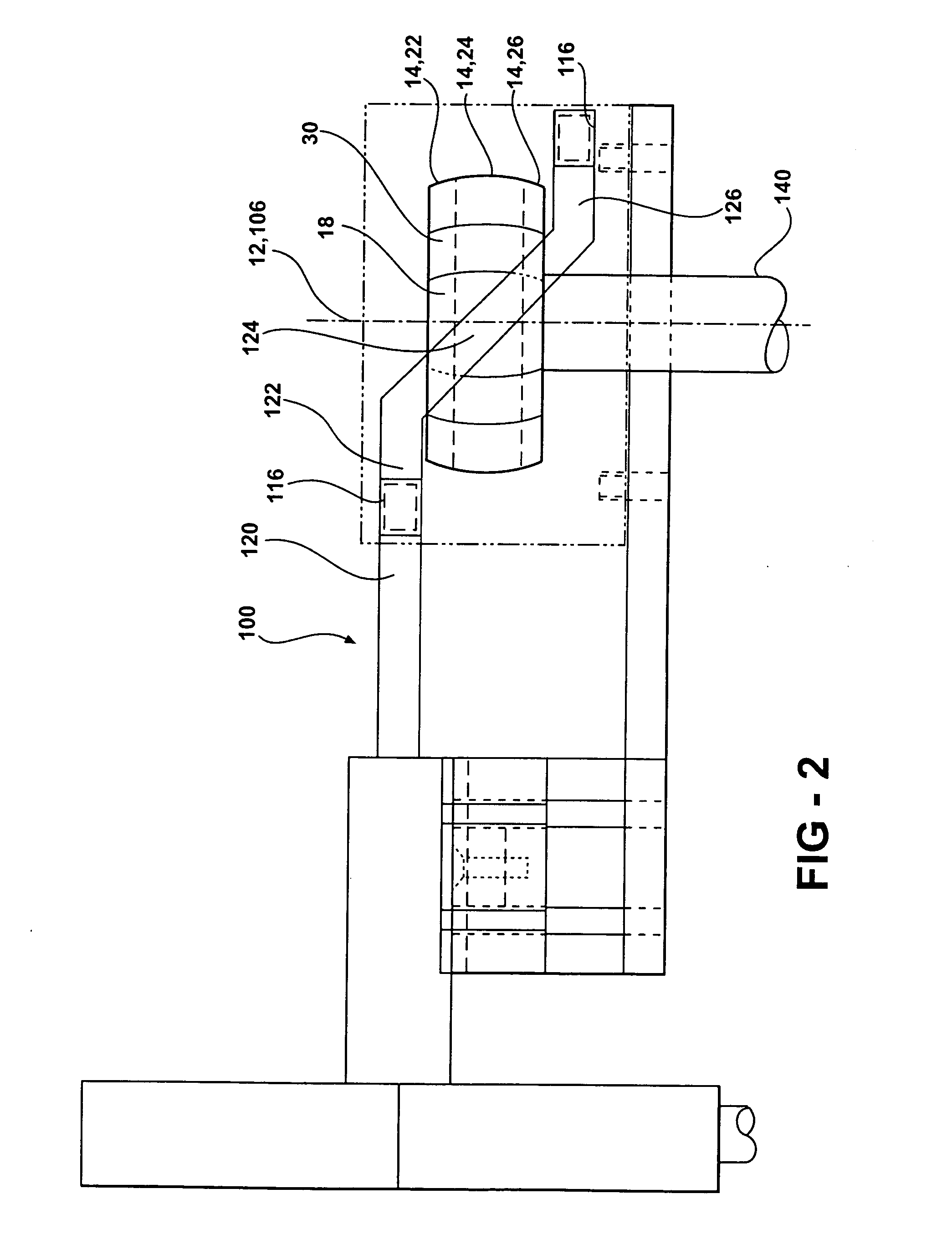
[0023] Referring to FIGS. 1-3, the present invention generally comprises a method of induction heat treatment 200 of a metal article 10 by means of an induction coil 100, and comprises the steps of: selecting 210 an article 10 for heat treatment having a longitudinal axis of rotation 12 and an outer surface 14 having an upper section 26, a lateral section 27 and a lower section 28, and comprising a plurality of points, such as d1 and d2 as illustrated in FIGS. 5 and 6, having a plurality of normal spacings from the axis of rotation; selecting 220 an induction coil 100 comprising a semi-cylindrical upper coil portion 102, a semi-cylindrical lateral coil portion 104, a semi-cylindrical lower coil portion 106 and a longitudinal axis 108, which is adapted to receive the article 10 for heat treatment and apply a non-planar magnetic field to the outer surface 14 of the article 10; placing 230 the article 10 within the induction coil 110; rotating 240 the article 10 within the induction co...


PUM

PropertyMeasurementUnit
Temperatureaaaaaaaaaa
Widthaaaaaaaaaa
Widthaaaaaaaaaa

Abstract

A method of induction heat treating the outer surface of articles having an irregular surface shape. The method employs an induction coil that provides a non-planar magnetic field that is adapted to the irregular shape of the article, such that distinct sections of the induction coil produce distinct magnetic fields that are adapted to induce currents in, and thereby provide heat to, distinct sections of the outer surface of the article. The method and induction coil are particularly adapted to provide an induction hardening heat treatment for the outer surfaces of the inner races of Rzeppa-type constant velocity joints.

Description

FIELD OF THE INVENTION [0001] The present invention relates to a method of induction heat treatment. More specifically, the invention comprises a method for induction hardening certain metal components, particularly those having a shape that prevents uniform induction coupling over the surface which is to be hardened. Most particularly, the invention comprises a method for induction hardening the steel inner race of Rzeppa-type constant velocity joints. BACKGROUND OF THE INVENTION [0002] Induction heat treatment is known to be an effective method of case hardening steels having a microstructure comprising a mixture of pearlite and ferrite. For example, induction hardening has been widely used for the case hardening of various types of steel gears. However, induction hardening has significant limitations in cases where the surface requiring heat treatment is irregular, such as gears having relatively larger teeth where the distance from the tip to the root of a tooth is such that the...

Claims


Application Information

Patent Timeline
IPC IPC(8): C21D1/10C21D1/18C21D9/00C21D9/32C21D9/40H05B6/14H05B6/36
CPCC21D1/10C21D1/18C21D9/0068H05B6/36C21D9/40C21D2211/008C21D2261/00C21D9/32Y02P10/25
Inventor CHRISTOFIS, MARKHOPSON, MICHAEL WALTERSZCZOMAK, TEDSZALONY, NORMANSAMS, ROBERT W.SEIDEL, RICHARD LAWRENCEBOGEN, WILLIAM PAUL
Owner FORD MOTOR CO
Why Eureka
Try Eureka