Apparatus and method for separating and filtering particles and organisms from flowing liquids
- Summary
- Abstract
- Description
- Claims
- Application Information
AI Technical Summary
Benefits of technology
Problems solved by technology
Method used
Image
Examples
Embodiment Construction
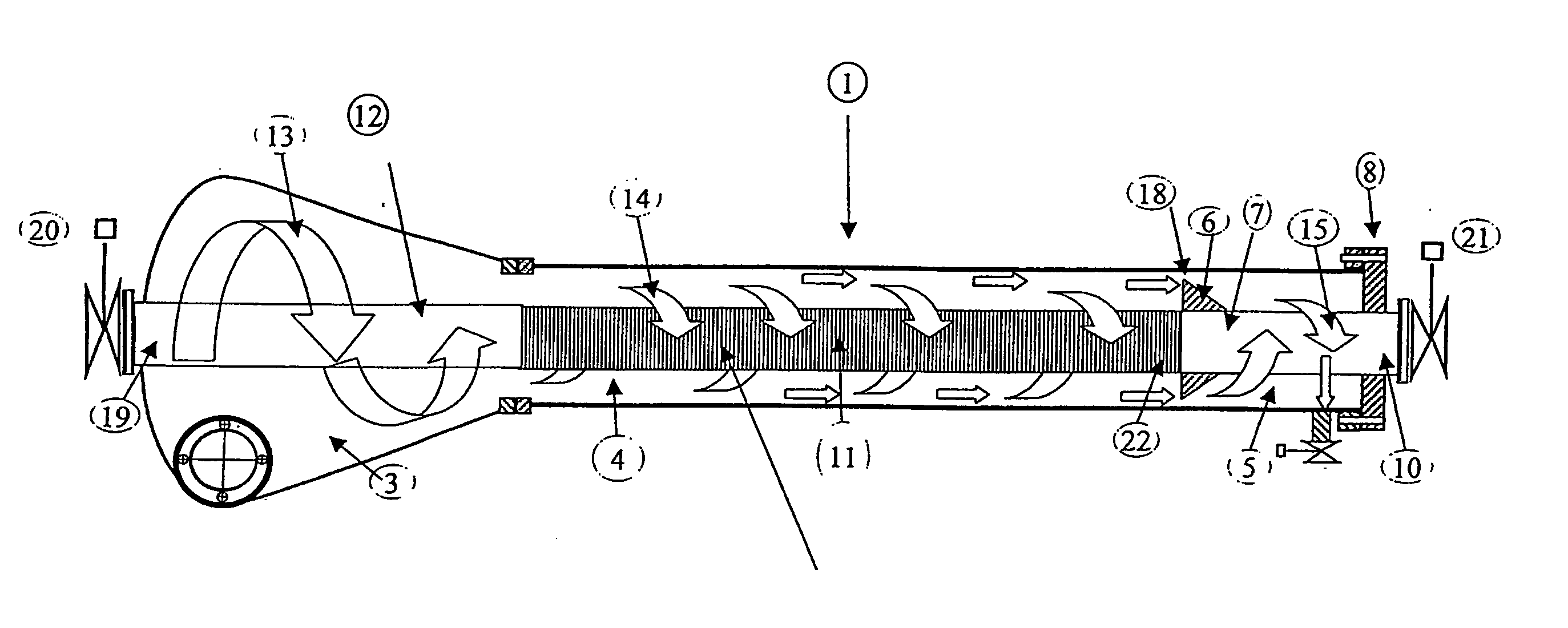
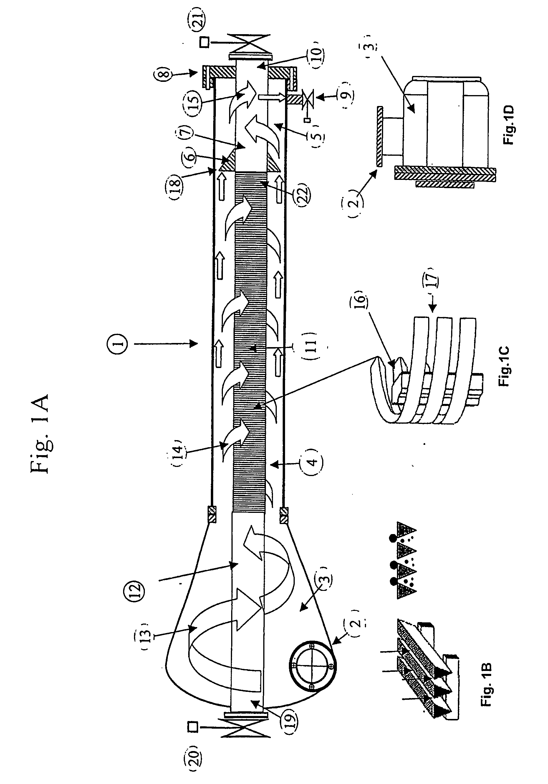
[0027] Referring to FIG. 1A of the drawing, the principal components of the liquid separator and filter device (1) are inlet chamber (3), separation and filter chamber (4), sludge chamber (5), and longitudinally disposed upper outlet pipe (19), cylindrical filter element (11) and lower outlet pipe (10).
[0028]FIG. 1A shows the filter and separator device (1), where the high volume, lower pressure liquid inlet (2) is mounted tangentially to circular inlet chamber (3) which is, in turn, connected to the separation and filter chamber (4). The inlet chamber is designed to meet the least possible fluid flow resistance and directs pumped liquid (13) in a helical circular motion around the longitudinal upper outlet pipe (19) which passes through the center of the inlet chamber (3). The liquid (13) forms a circular spinning flow into and through the separation and filter chamber (14) without forming a vortex as in traditional hydro-cyclones. The liquid (13) accelerates in the inlet chamber ...
PUM
| Property | Measurement | Unit |
|---|---|---|
| Fraction | aaaaa | aaaaa |
| Nanoscale particle size | aaaaa | aaaaa |
| Pressure | aaaaa | aaaaa |
Abstract
Description
Claims
Application Information
 - R&D
- Intellectual Property
- Life Sciences
- Materials
- Tech Scout
- Unparalleled Data Quality
- Higher Quality Content
- 60% Fewer Hallucinations
Browse by: Latest US Patents, China's latest patents, Technical Efficacy Thesaurus, Application Domain, Technology Topic, Popular Technical Reports.
© 2025 PatSnap. All rights reserved.Legal|Privacy policy|Modern Slavery Act Transparency Statement|Sitemap|About US| Contact US: help@patsnap.com


