Thermoforming method and apparatus

a vacuum forming and thermoplastic technology, applied in the field of thermoforming, can solve the problems of inability to provide uniform temperature across the mold, the coolant line is a significant the coolant line is a common obstacle to the formation of vacuum holes, so as to reduce the need for conventional coolant lines, reduce cycle time, and simple and effective thermoforming

Inactive Publication Date: 2005-02-24
CORVAC COMPOSITES
View PDF5 Cites 25 Cited by
  • Summary
  • Abstract
  • Description
  • Claims
  • Application Information

AI Technical Summary

Benefits of technology

[0015] The present invention provides a simple and effective thermoforming method and apparatus that reduces cycle time and is manufactured with only limited changes in conventional mold manufacturing techniques. Because the thermoforming apparatus includes a quench for cooling the sheet, the need for conventional coolant lines is eliminated. This facilitates manufacture of the mold by eliminating the effort needed to avoid the coolant lines when creating vacuum holes in the manufactured mold. Furthermore, use of the quench provides rapid cooling of the thermoplastic sheet at uniform and controlled temperature.

Problems solved by technology

Conventional coolant line arrangements suffer from several significant drawbacks.
First, coolant lines present an obstacle with respect to the formation of the vacuum holes 20 in the mold 14.
Second, coolant lines typically do not provide uniform temperature across the mold.
This results in non-uniform cooling along the sheet 18.
Third, with complex molds, it can be difficult or impossible to locate cooling lines in certain areas of the mold.
This reduces the cooling effect of the coolant lines in such areas.
Although providing some improvement, these techniques are not without drawbacks.
Second, misting devices, particularly nitrogen misting devices, can be expensive to install and operate.

Method used


Image

  • Thermoforming method and apparatus
  • Thermoforming method and apparatus
  • Thermoforming method and apparatus

Examples


first alternative embodiment

IV. First Alternative Embodiment

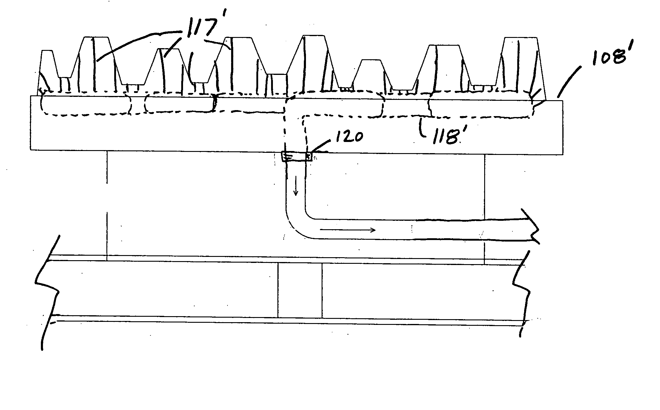
[0058] A first alternative embodiment of the present invention is shown in FIGS. 13 and 14. This embodiment includes most of the same components of the preferred embodiment, except the drive assembly. The hydraulic cylinders 264a-d are similar to the hydraulic cylinders of the preferred embodiment, except that the rams 265a-d preferably are telescoping and that the carriage 272 is fixed to the carriage supports 273a-d, a distance below the tops of the supports 278a-d. In operation, the mold 208 is lifted in unison by the hydraulic telescoping cylinders 264a-d to engage a sheet 104 supported on the rack 202b in a manner identical to that of the preferred embodiment. The mold 208 is shown in the raised position in FIG. 13 in phantom lines. When the mold208 is withdrawn with the sheet 104 vacuum drawn against it, rather than rotating, the carriage platen 272 is drawn downward in unison by the hydraulic cylinders 264a-d, until as shown in phantom lines in...

second alternative embodiment

V. Second Alternative Embodiment

[0059] A second alternative embodiment of the present invention is shown in FIG. 15. The forming apparatus shown in FIG. 15 generally includes an inverted mold 308 mounted to carriage 372 which is further mounted to inverted hydraulic cylinders 364a-d. In operation, the hydraulic cylinders lower carriage 372 and mold 308 down through rack arm 302b so that the sheet 104 may be drawn against the mold 308 as described in the preferred embodiment. The carriage 372 is further descended in unison by the hydraulic cylinders 364a-d so that the mold 308 and sheet 104 associated with it are positioned in the quenching tank 313 where the liquid 314 is permitted to cool the sheet 104. The mold 108 is shown in the fully lowered position in FIG. 15 in phantom lines. Once the sheet 104 is sufficiently cooled it may be withdrawn on the mold 308 via the hydraulic cylinders 364a-d. The sheet 104 may be removed from the mold with any of the techniques described in conne...

third alternative embodiment

VI. Third Alternative Embodiment

[0060] A third alternative embodiment is shown in FIG. 16. As shown in FIG. 16, the forming apparatus generally includes an inverted mold 408 similar to the inverted mold of the second alternative embodiment. The mold 408 is mounted to a carriage 472 which is further mounted to inverted hydraulic cylinders 464a-d. Actuation of the cylinders 464a-d moves the mold vertically between a first position shown in solid lines in FIG. 16 and a second position shown in phantom lines in FIG. 16. In addition, the reservoir 413 of the quench 410 is mounted to a plurality of vertically extending hydraulic cylinders 450a-d. As shown, the reservoir 413 is conventionally mounted to the cylinders 450a-d such that the bottom surface 452 of the reservoir rests on top of the cylinders 450a-d. Alternatively, the quench may be mounted to a carriage similar to the carriage 472, or otherwise conventionally attached to the cylinders 450a-d. The cylinders 450a-d can be actuated...


PUM

PropertyMeasurementUnit
perimeteraaaaaaaaaa
sizeaaaaaaaaaa
temperatureaaaaaaaaaa

Abstract

A thermoforming apparatus having a mold with an internal vacuum chamber and a quench for cooling a thermoplastic sheet while it remains on the mold. Because the quench cools the sheet, conventional cooling lines are eliminated from the mold. One method of using the thermoforming apparatus includes pushing a heated sheet towards the mold with a plug assist, drawing the heated sheet over the mold, creating a partial vacuum in the vacuum chamber of the mold to maintain the sheet on the mold and quenching the sheet on the mold in a quenching tank by moving the quenching tank to the mold.

Description

BACKGROUND OF THE INVENTION [0001] This application is a continuation-in-part of U.S. Ser. No. 09 / 951,176, filed Sep. 13, 2001, by James Richard Fitzell, Jr.[0002] The present invention relates to thermoforming and more particularly to a method and apparatus for vacuum forming thermoplastics. [0003] Thermoforming is widely used in a variety of industries to manufacture products from thermoplastic materials, such as high-density polyethylene (“HDPE”). Many different thermoforming processes are currently in widespread use, including vacuum forming, blow molding and the like. A typical thermoforming process involves the general steps of heating a thermoplastic material above its glass-transition temperature, shaping the heated thermoplastic by drawing the material over a mold, cooling the thermoplastic to a low enough temperature for it to retain its shape and then removing the shaped thermoplastic from the mold. [0004] Vacuum forming is perhaps one of the most versatile thermoforming ...

Claims


Application Information

Patent Timeline
Patent Type & Authority Applications(United States)
IPC IPC(8): B29C51/36B29C33/38B29C35/08B29C35/16B29C51/08B29C51/10B29C51/22B29C51/26B29C51/42B29C51/46
CPCB29C33/38B29K2023/065B29C51/08B29C51/10B29C51/22B29C51/261B29C51/36B29C51/42B29C51/46B29C2035/0822B29C2035/1616B29C2035/1625B29C2035/1633B29C2791/006B29C35/16
Inventor FITZELL, JAMES RICHARD JR.
Owner CORVAC COMPOSITES
Why Eureka
Try Eureka