Periodic interface calibration for high speed communication

Inactive Publication Date: 2005-02-24
RAMBUS INC
View PDF57 Cites 62 Cited by
  • Summary
  • Abstract
  • Description
  • Claims
  • Application Information

AI Technical Summary

Benefits of technology

[0010] The present invention provides a communications interface, including transmitters and receivers, adapted for periodic calibration, and a method for maintaining calibration of communication paths across the interface. The periodic calibration process can oper

Problems solved by technology

One problem which becomes more important as communication speeds increase is calibration of clocks and sample timing.
High-frequency noise, known as jitter, places a cloud of uncertainty around this optimal sampling point.
Methods to compensate for jitter have been limited in effectiveness.
However, there is

Method used


Image

  • Periodic interface calibration for high speed communication
  • Periodic interface calibration for high speed communication
  • Periodic interface calibration for high speed communication

Examples


Embodiment Construction

[0029] A detailed description of embodiments of the present invention is provided with reference to FIGS. 1-5.

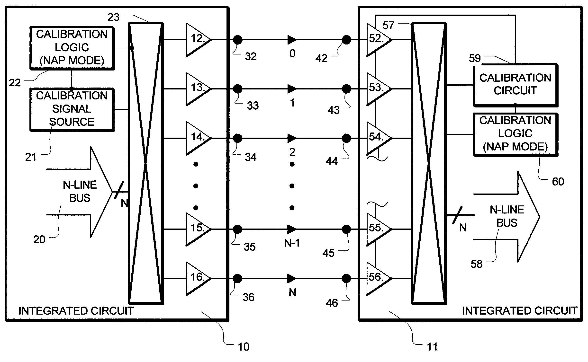
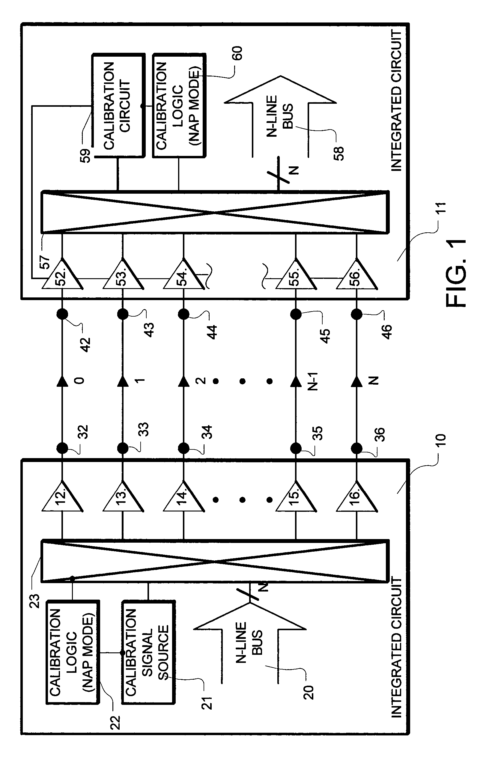
[0030]FIG. 1 is a simplified block diagram of the communication system applying continuous periodic calibration according to the present invention. The system includes a first integrated circuit 10 and a second integrated circuit 11. The first integrated circuit 10 includes a logical layer parallel bus 20 including N lines, a calibration signal source 21, and calibration logic 22. A switch 23 couples the parallel bus 20 and the calibration signal source 21 with a set of transmitters 12-16, including one for each of N+1 physical layer communication lines. The set of transmitters 12-16 drives communication signals across communication media. In this example, the set of transmitters 12-16 drive data on signal lines coupled to input / output ports 32-36 (such as IO pins on the integrated circuit), which are coupled to respective transmission lines, including line 0 through line N...


PUM


Abstract

A high-speed communication interface manages a parallel bus having N bus lines. N+1 communication lines are established. A maintenance operation is performed on one of the N+1 communication lines, while N of the N+1 communication lines is available for data from the N line bus. The communication line on which the maintenance operation is performed, is changed after the operation is complete, so that all of the N+1 communication lines are periodically maintained, without interfering with communications on N of the N+1 communication lines.

Description

BACKGROUND OF THE INVENTION [0001] 1. Field of the Invention [0002] The present application relates to high-speed communication interfaces, including high-speed parallel bus interfaces for integrated circuits; and more particularly to calibration of such interfaces. [0003] 2. Description of Related Art [0004] High-performance data processing applications are driving the demand for data rates past the GigaHertz range. As processor clock speeds increase to meet the demand, high-performance parallel bus interface technology is being developed to meet these needs. In parallel bus interfaces, a number of serial lines are operated in parallel. So-called SERDES (short for serializer-deserializer) technologies are being applied for each of the parallel lines. Other high-performance bus interface technologies are provided by Rambus, Inc., including products provided under the tradenames XDR™ High Performance Memory Interface Technology, Raser™ High Performance Interface Technology, and Redwo...

Claims


Application Information

Patent Timeline
IPC IPC(8): H01LH03M9/00H04L7/00H04L7/04H04L7/10H04L12/66H04L25/14
CPCH03M9/00H04L7/0008H04L25/14H04L7/10H04L7/043H04L12/66H04L12/28
Inventor KIZER, JADE M.
Owner RAMBUS INC
Why Eureka
Try Eureka