Passive optical network using error correction code

a technology of error correction and optical network, applied in the field of optical network, can solve the problems of discontinuous optical signals having intensities that change, optical communication networks formed in star or bus configurations have a number of limitations, and the initial installation of the ptp network is very expensive, so as to reduce the noise of optical beat interference, increase the transmission speed of the optical network unit, and increase the number of subscribers connected

Inactive Publication Date: 2005-02-24
SAMSUNG ELECTRONICS CO LTD
View PDF4 Cites 26 Cited by
  • Summary
  • Abstract
  • Description
  • Claims
  • Application Information

AI Technical Summary

Benefits of technology

[0027] An other object of the present invention to provide a passive optical network using error correction codes, which decreases the optical beat interference noise by actively controlling the light source of the optical network unit in order to incr

Problems solved by technology

However, the PTP network requires a very large cost for initial installation of the network.
Optical communication networks that are formed in a star or bus configuration have a number of limitations in upstream transmission.
He discontinuous optical signals have intensities which change greatly due to difference between physical distances and signal losses according to subscribers.
Typically, it is difficult to realize a high speed burst mode receiver, and thus it is difficult for networks using the burst mode receiver to conduct high speed operation.
However, the WDM requires expensive light sources due to subscribers using light sources having different wavelengths.
However, when the CD

Method used


Image

  • Passive optical network using error correction code
  • Passive optical network using error correction code
  • Passive optical network using error correction code

Examples


Embodiment Construction

[0035] Hereinafter, preferred embodiments of the present invention will be described in detail with reference to the accompanying drawings. Note that the same or similar components in drawings are designated by the same reference numerals as far as possible even if they are shown in different drawings. In the following description of the present invention, a detailed description of known functions and configurations incorporated herein will be omitted when it may make the subject matter of the present invention rather unclear.

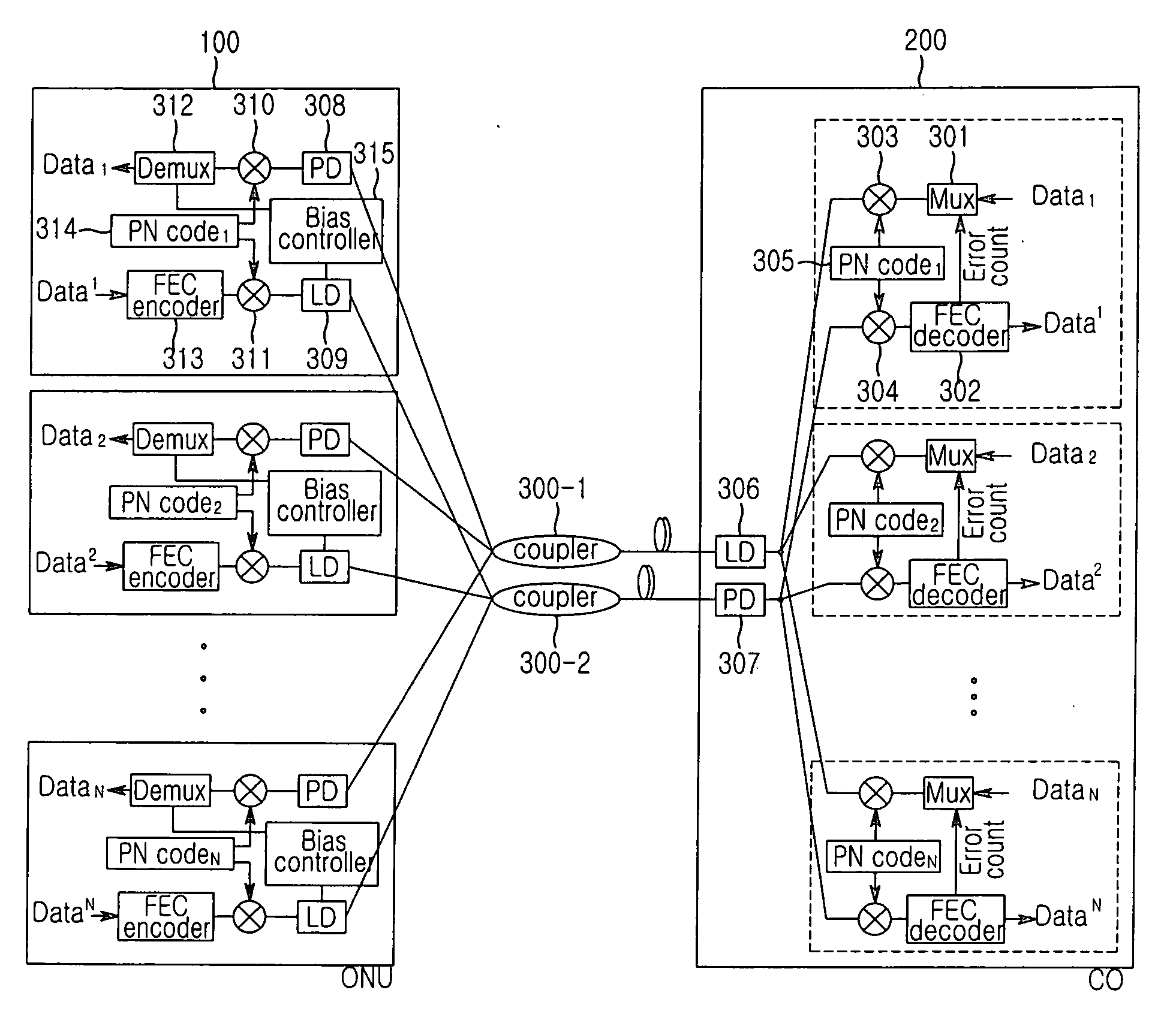
[0036]FIG. 3 illustrates a CDMA passive optical network using error correction codes according to an embodiment of the present invention.

[0037] In general, a CDMA passive optical network discriminates each subscriber using a CDMA mode and overcomes optical beat interference noise using a processor gain. However, as described above, as subscribers increase, conventional optical networks cannot sufficiently overcome the optical beat interference noise using onl...


PUM


Abstract

Disclosed is a passive optical network of code division multiple access using error correction code, which includes a plurality of optical networks units (ONU) and a central office, assigns a pseudo-noise (PN) code to each ONU, and transfers optical signals modulated by the PN code between the central office and each ONU, the passive optical network comprising the ONU which inserts error correction codes into upstream signals, transmits the upstream signals to the central office, and controls frequencies of the upstream signals using a response of the central office for the transmitted error correction codes and the central office which receives the upstream signals code division-encoded, decodes the upstream signals, inserts error counts of the error correction code included the upstream signals into downstream signals for the ONU, and transmits the downstream signals to the ONU.

Description

CLAIM OF PRIORITY [0001] This application claims priority to an application entitled “CDMA passive optical network using error correction code,” filed in the Korean Intellectual Property Office on Aug. 21, 2003 and assigned Serial No. 2003-58024, the contents of which are hereby incorporated by reference. BACKGROUND OF THE INVENTION [0002] 1. Field of the Invention [0003] The present invention relates to an optical network, and more particularly to a passive optical network using a Code Division Multiple Access mode and an error correction code. [0004] 2. Description of the Related Art [0005] A passive optical network (PON) has no active equipment except terminal equipment of the network outside the plant. An active optical network (AON) needs an active equipment outside the plant. Passive optical network are realized at a lower cost and are more easily maintained and managed than active optical networks. [0006] In general, passive optical networks are realized in stars, buses and p...

Claims


Application Information

Patent Timeline
IPC IPC(8): H04B10/077H04B10/27H04B10/079H04B10/2507H04B10/272H04B10/524H04B10/572H04J14/00H04J14/02H04J14/04H04J14/06H04L1/00H04L12/44
CPCH04J14/02H04L1/0001H04L1/0056H04L1/0045H04L1/0026H04B10/00H04B10/272H04B10/25
Inventor KIM, HOONHWANG, SEONG-TAEK
Owner SAMSUNG ELECTRONICS CO LTD
Why Eureka
Try Eureka