
Manufacturing assembly line and a method of designing a manufacturing assembly line

Inactive Publication Date: 2005-03-03
FORD MOTOR CO
View PDF45 Cites 86 Cited by
  • Summary
  • Abstract
  • Description
  • Claims
  • Application Information

AI Technical Summary

Benefits of technology

[0006] A fundamental requirement of any successful automobile manufacturing company is an ability to mass produce a variety of different vehicles very efficiently, year after year and model after model in a number of manufacturing plants that are located in one or more countries. It is desirable to both reduce the amount of capital investment required and provide greater manufacturing flexibility at the same time. It would be advantageous to shorten the time required to complete a model changeover and enable the same automobile manufacturing plant to rapidly switch over to produce different vehicle types. It would also be desirable to reuse a large percentage of existing manufacturing equipment when a different vehicle type or platform is to be manufactured. It is also important to leverage an automobile company's knowledge of component parts of a manufacturing system over time. Finally, it would be desirable to achieve these manufacturing efficiency benefits without requiring that all of the existing automobile plants in the company's manufacturing system undergo transformation at the same time.
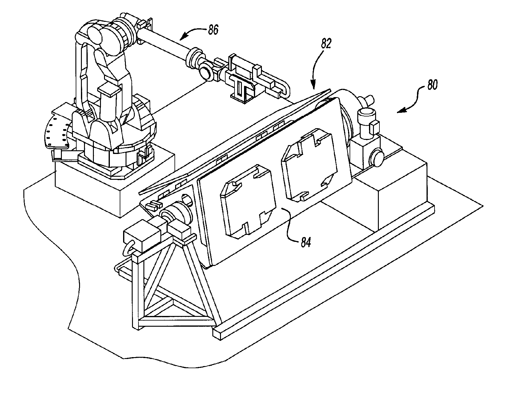
[0053] Referring to FIGS. 20, 21 and 22, the dash panel template, cowl top template 210, and front structure template 220 are described in more detail. Each template 200, 210, 220 is made up of a number of work cells. The flow of material between work cells is represented by arrowed lines. Optionally, each template may employ one or more decoupling stations to provide a buffer between stations to improve material flow.

Problems solved by technology

Modern automobile manufacturing operations are extremely complicated.
While it is possible to add flexibility to robot paths and reach to weld different automobile body styles on a common or similar vehicle platform, the flexibility provided by such adjustments is limited.

Method used


Image

  • Manufacturing assembly line and a method of designing a manufacturing assembly line
  • Manufacturing assembly line and a method of designing a manufacturing assembly line
  • Manufacturing assembly line and a method of designing a manufacturing assembly line

Examples


Embodiment Construction

)

[0019] Vehicle manufacturing systems generally comprise a process line for assembling the body of an automotive vehicle. Metal components of the body assembly for an automotive vehicle are created in a metal stamping facility. In some instances, metal stamping facilities are located next to a vehicle assembly plant. However, most stamping facilities are remote from assembly facilities which necessitates that the stamped metal workpieces be shipped by rail or truck to an assembly plant.

[0020] Upon arrival at the assembly plant, stamped workpieces are delivered to the body shop of the assembly facility. In the body shop, the shell of the vehicle is assembled on a weld processing line. After the shell of the vehicle is assembled on the weld processing line, the body is delivered to the paint shop of the assembly plant where the body is painted. The prime coat applied to the body shell is white and the term “body-in-white” is often used to refer to the body assembly.

[0021] After the ...


PUM

PropertyMeasurementUnit
Flexibilityaaaaaaaaaa
Configurationaaaaaaaaaa

Abstract

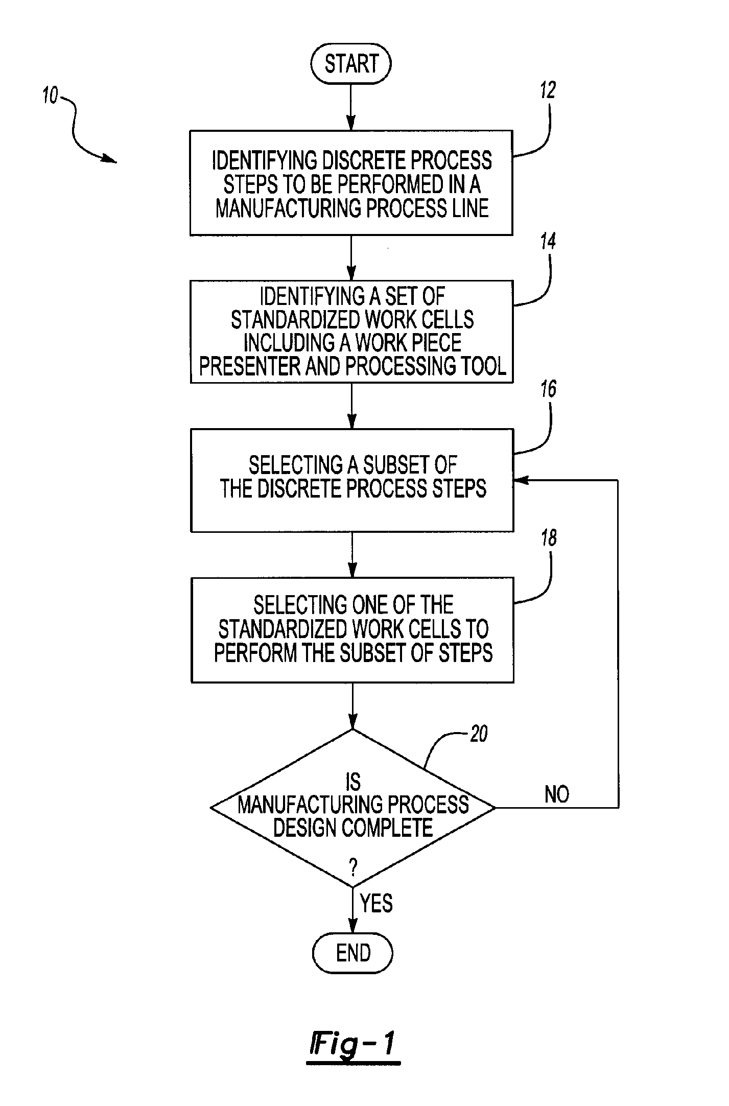
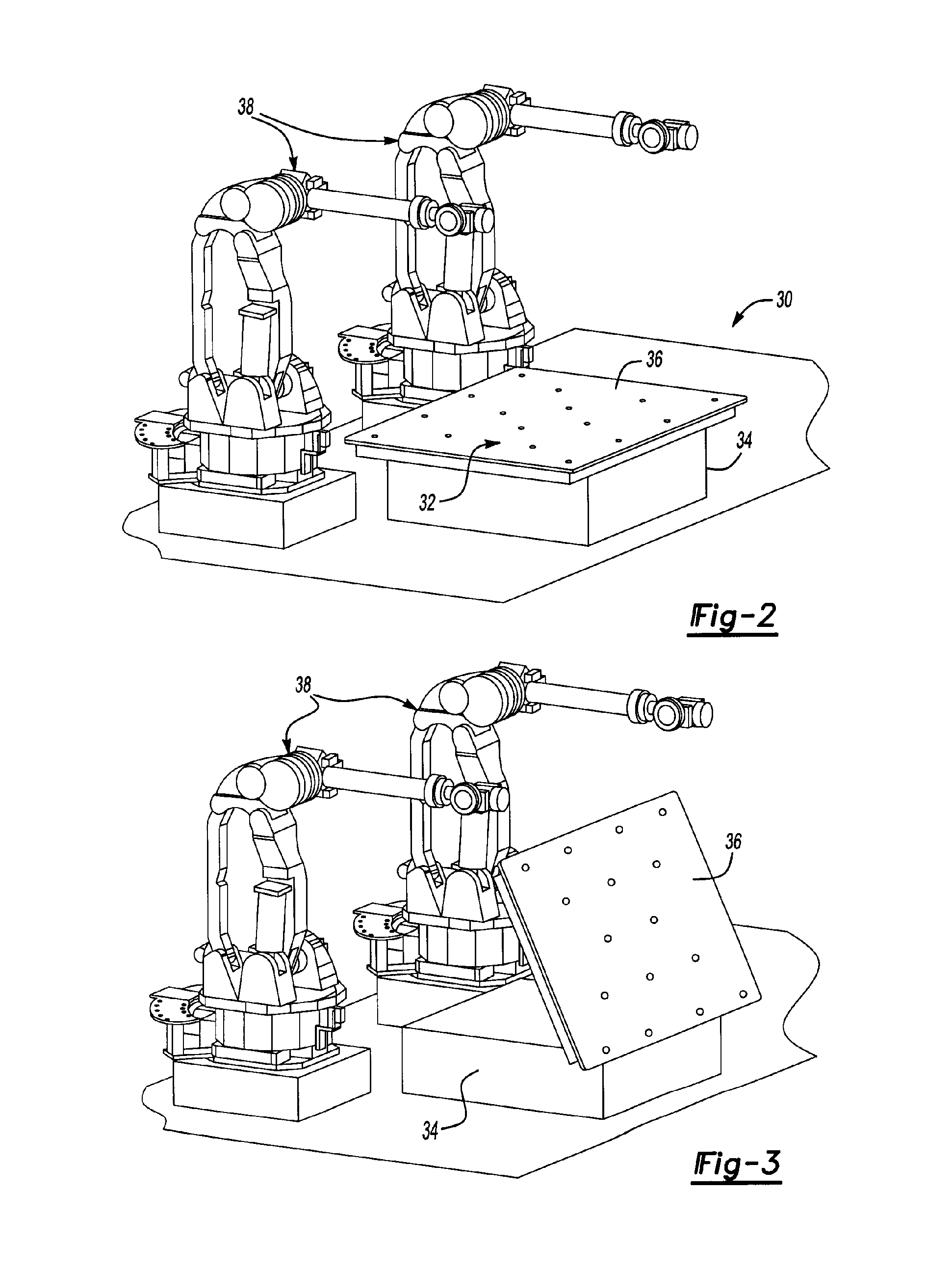
A method of designing a manufacturing process line. A process is identified as a set of discrete steps. A subset of steps is assigned to one of a plurality of standardized work cells. The work cells include a standardized workpiece presenter and a standardized processing tool. Additional subsets of discrete steps are assigned to a standardized work cell until the design for the manufacturing process is completed.

Description

CROSS REFERENCE TO RELATED APPLICATIONS [0001] This application is a continuation of U.S. application Ser. No. 10 / 708,817 filed Mar. 26, 2004, which is a division of U.S. application Ser. No. 10 / 253,169, filed Sep. 24, 2002 and U.S. application Ser. No. 10 / 253,686, filed Sep. 24, 2002.BACKGROUND OF THE INVENTION [0002] 1. Field of the Invention [0003] The present invention relates to a flexible system for designing a manufacturing line for complex body units, and more particularly to a manufacturing process line and a method of developing a manufacturing process that standardizes the use of flexible systems utilized in manufacturing vehicle bodies. [0004] 2. Background and Summary of the Invention [0005] The automobile industry is a capital intensive environment with extensive multinational competition and international company alliances. To be competitive, an automobile company must be in a position to offer a range of different vehicles on a global scale and be in a position to ra...

Claims


Application Information

Patent Timeline
IPC IPC(8): B23K37/04B23P21/00B23Q1/52B23Q1/54B23Q16/00B25J17/02B62D65/02B62D65/18G05B19/418
CPCB23K37/0426Y10T29/534B23K2201/006B23P21/004B23P2700/50B23Q1/52B23Q1/5462B23Q16/001B25J17/0216B62D65/02B62D65/18G05B19/41805G05B2219/31044Y10T29/49828Y10T29/53417B23K37/0452B23K2101/006Y02P90/02
Inventor GHUMAN, ABIDLOWE, JAMESROSSO, MARSHASANBORN, KIRK
Owner FORD MOTOR CO
Learn More