
Upgraded emissions reduction system

Inactive Publication Date: 2005-03-03
KLEENAIR SYST
View PDF10 Cites 13 Cited by
  • Summary
  • Abstract
  • Description
  • Claims
  • Application Information

AI Technical Summary

Benefits of technology

[0003] In accordance with one embodiment of the present invention, applicant further reduces nitrogen oxides in the exhaust gases of vehicle engines that are already reduced by the injection of ammonia and its components into the exhaust gases. The further reduction is achieved by converting a maximum portion of the nitric oxide (NO) in the exhaust gases into nitrogen dioxide (NO2). The injected ammonia and ammonia components react catalytically much faster and more completely with nitrogen dioxide (NO2) than with nitric oxide (NO), resulting in less nitrogen oxides released into the atmosphere.
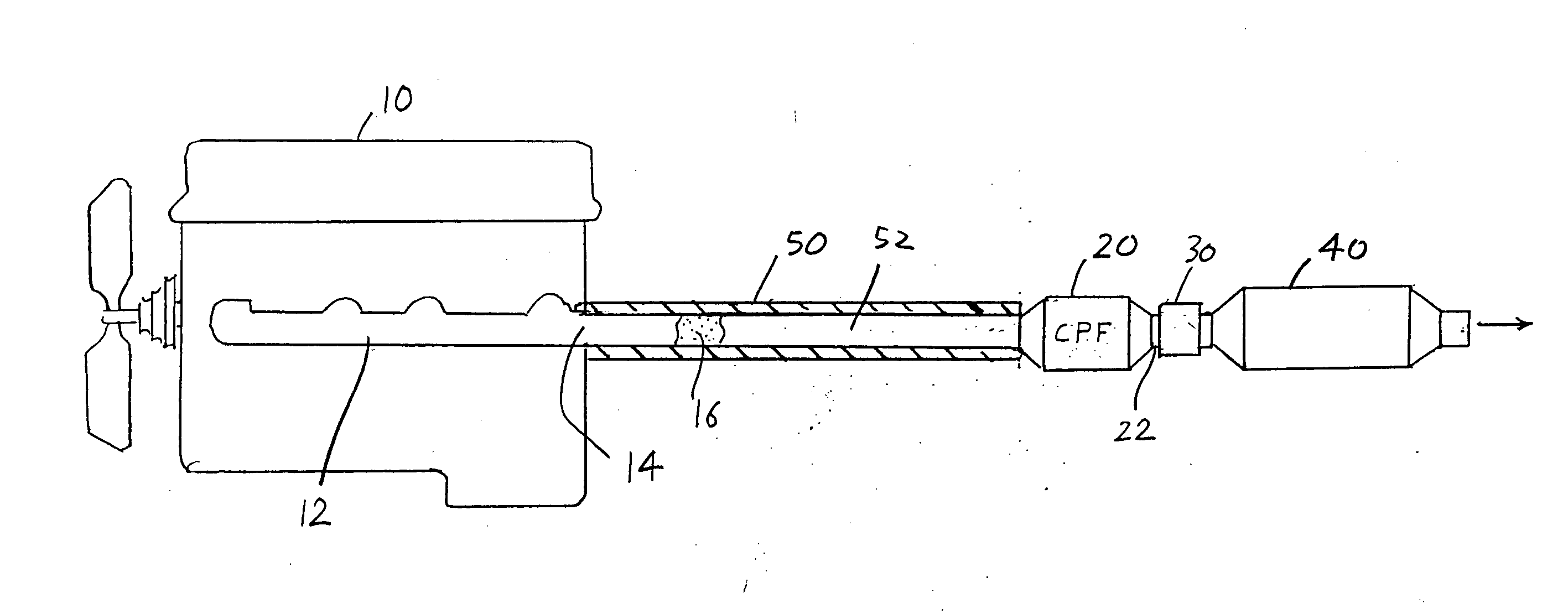
[0005] In some vehicles such as diesel buses, there is no room to place a catalyzed particulate filter (CPF) at the end of the exhaust gas manifold except at least about a meter rearward of the manifold. Previously, this resulted in a large temperature drop of the exhaust gases before they reached the first catalyst, and an even further drop before the exhaust gases reach applicant's ammonia injector station. Applicant mitigates this by wrapping insulation about the exhaust gas conduit portion that extends between the exhaust gas manifold and the long (at least about a meter, but even if one-eighth meter long) conduit portion. The insulation reduces the temperature drop so the temperature is at least 30° C. higher than the temperature that would exist in the absence of such insulation.

Problems solved by technology

Previously, this resulted in a large temperature drop of the exhaust gases before they reached the first catalyst, and an even further drop before the exhaust gases reach applicant's ammonia injector station.

Method used


Image

  • Upgraded emissions reduction system
  • Upgraded emissions reduction system

Examples


Embodiment Construction

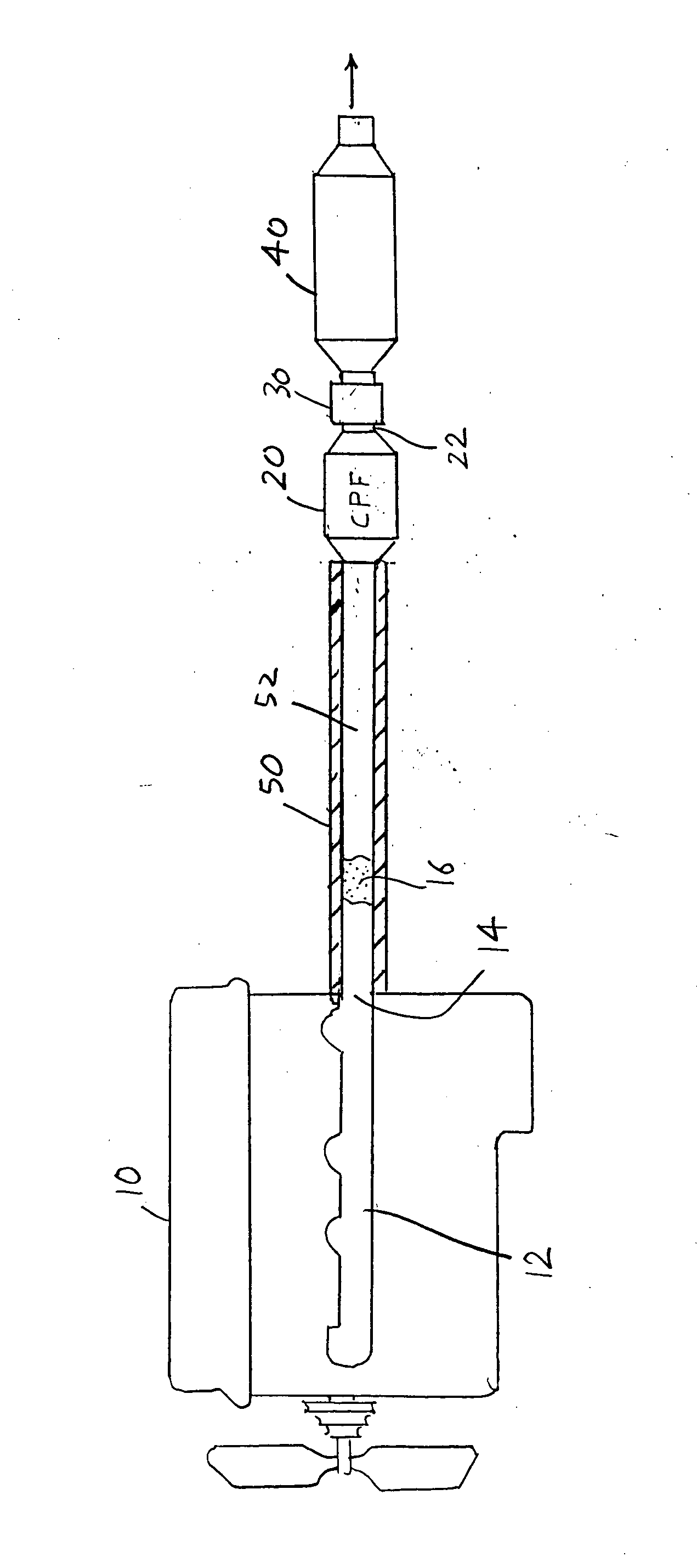
[0008] The FIGURE illustrates a diesel engine 10 with an exhaust manifold 12 that combines the exhaust from all engine cylinders and passes the exhaust gases 16 from the manifold outlet 14 through a conduit 52. The exhaust gases pass through a CPF (catalyzed particulate filter) 20, through an ammonia injection station 30, and through a catalytic converter 40. The catalytic converter is preferably a NOxMASTER SCR / DOC catalytic converter. The catalyst in the catalytic converter helps react ammonia (NH3) with nitrogen oxides in the exhaust gasses. It also reacts oxygen with carbon and carbon monoxide in the exhaust gases to reduce unburned carbon particles and produce carbon dioxide.

[0009] Applicant's experiments show that ammonia (NH3) and ammonia components (NH2 and / or NH+H) react much faster and more completely with nitrogen dioxide (NO2) than with nitric oxide (NO). Applicant also finds that the CPF (catalyzed particulate filter) 20, which is used to reduce soot in diesel engine e...


PUM


Abstract

A system is provided that reduces nitrogen oxides in the exhaust gases of an engine by converting nitric oxide (NO) in the exhaust gases to nitrogen dioxide (NO2) prior to injecting ammonia (NH3) into the exhaust gases, and then passing the exhaust gases through a vehicle catalytic converter. Much of the nitric oxide (NO) is converted to nitrogen dioxide (NO2) by passing the exhaust gases first through a catalyzed particulate filter (CPF) such as one containing a nitric oxide catalyst. In cases where the exhaust gases must pass from the exhaust gas manifold through an exhaust conduit portion of a length of at least one-eighth meter before reaching the catalyzed particulate filter, that exhaust conduit portion is heavily insulated to result in a high exhaust gas temperature at the downstream end of that conduit portion by at least 30° C. over the temperature without insulation.

Description

CROSS REFERENCE [0001] Applicant claims priority from U.S. provisional application Ser. No. 60 / 498,766 filed Aug. 29, 2003.BACKGROUND OF THE INVENTION [0002] Our earlier U.S. Pat. No. 5,992,141 describes the injection of activated ammonia into hot exhaust gases of vehicle engines, to reduce nitrogen oxides (NO and NO2) which are sometimes referred to as NOX and which is a major component of smog. The injected ammonia (NH3) reacts with nitrogen oxides (NO and NO2) in the exhaust gases to produce nitrogen and water vapor. While the system described in the above patent reduces nitrogen oxides, some nitrogen oxides are still present in the exhaust gases that are released into the atmosphere. More stringent air quality standards require that the amount of nitrogen oxides be reduced even further. SUMMARY OF THE INVENTION [0003] In accordance with one embodiment of the present invention, applicant further reduces nitrogen oxides in the exhaust gases of vehicle engines that are already redu...

Claims


Application Information

Patent Timeline
IPC IPC(8): B01D53/94F01N3/023F01N3/035F01N3/20F01N13/02F01N13/14
CPCB01D53/9431F01N3/0231F01N3/035F01N3/2066F01N13/009F01N2340/02F01N2610/02Y02T10/24F01N13/14Y02T10/12Y02A50/20
Inventor BERRIMAN, LESTER P.SIMONS, LIONEL S.ZABSKY, JOHN M.
Owner KLEENAIR SYST
Learn More